0 引言
丰富的矿产资源是现代工业和经济快速发展的重要前提,随着浅层矿产资源的逐渐减少,对深部金属矿勘探提出了更高的要求[1 3] 。激电法作为一种多功能的地球物理勘探方法,在了解地质结构、寻找地下水和金属矿勘探中有着非常广泛的应用[4 7] 。然而,该方法在进行频散率和相位测量时容易受到电磁耦合的影响,特别是在大深度或低阻勘探过程中,电磁耦合效应更加强烈,从而对激电信号造成严重干扰[8 -9 ] 。
上述问题可以从硬件采集端和数据处理两个方面来解决。前者可通过增大发射电流提高数据采集信噪比,再经选频接收、相干检测等手段增强接收机抗干扰能力[10 13] 。后者主要是利用去耦方法对测量信号进行后处理,从而消除电磁耦合效应的影响,前人已经在这方面做了大量的工作,可总结分为3大类:
第一类是假设频率域激电效应的振幅随频率对数近似线性增加,而电磁耦合的振幅则随频率呈指数增加,从而可以通过两频校正方法去除电磁耦合效应[14 16] 。例如,郭鹏等[17 -18 ] 研究了中梯装置中电磁耦合效应的影响因素和频率特征,并利用两频校正方法消除了电磁耦合的影响。第二类是假设低频段激电效应的相位随频率变化不大,而电磁耦合引起的相位则随频率线性增大,从而可利用相对相位法进行线性校正。例如,陈儒军等[19 ] 基于这一特性推导了相对相位谱的计算公式,并通过实验证明相对相位谱测量不仅能有效抑制电磁耦合感应,还能消除由于发送机与接收机之间同步误差造成的影响。李栋等[20 ] 研究了偶极装置中的电磁耦合响应,并将相对相位法应用于实测激电资料的处理中,进一步验证了该去耦方法的有效性。第三类是根据电磁耦合效应和激电效应在时间域的差异进行斩波去耦。例如,向毕文等[21 ] 利用指数函数在时间域内对激电效应进行拟合,从而在保留激电信号的同时去除了电磁耦合效应,取得了良好的效果。
上述研究成果对激电信号的高质量提取有着重要的意义,但他们的研究对象均为浅层矿体,没有考虑在深部勘探中电磁耦合对激电信号的影响。在大深度勘探中,由于供电极距的增加导致电磁耦合强度增大,测量信号也会变得更加复杂,上述方法假设的有效性需要进一步的验证。为此,本文基于Thomas等[22 ] 发布的CR1Dmod开源程序对大深度激电中的电磁耦合效应进行研究,分析装置类型、布线方式、大地电阻率阻值和频率等因素对电磁耦合强度的影响。同时从相对相位谱的计算原理出发,分析其在处理大深度激电数据的适用性,并定量考察其在三极装置和四极装置中的去耦效果,得到的结论对大深度激电找矿的现场施工有一定的指导意义。
大深度激电法中的电磁耦合是利用激电法进行矿产勘探时,供电线路与测量线路之间的电性感应,主要包括电容耦合和电磁耦合。电容耦合是指供电线路与测量导线以及大地之间因存在分布电容而导致的假激电异常,Madden等[23 ] 通过研究证明,只要供电导线和测量导线之间的距离足够大,电容耦合的影响就可以忽略不计。因此,本文仅考虑外在因素对电磁耦合强度的影响。
1 电磁耦合计算原理
电磁耦合指的是发射导线和接收导线间随频率变化的互感应阻抗。Sunde[24 ] 在1968年指出地表任意两条接地导线之间的电磁耦合响应可以通过对ds 和dS 这两个偶极子的互阻抗沿各自的导线分别进行积分得到,并给出了其理论解,如式(1)所示:
(1) $Z={\int }_{A}^{B}{\int }_{M}^{N}\left[P\left(r\right)cos\theta +\frac{{\partial }^{2}Q\left(r\right)}{\partial s\partial S}\right]dsdS,$
式中:ds 和dS 分别是测量导线MN 和供电导线AB 上面的线元;r 为两个线元之间的距离;θ 是两个线元之间的夹角。为了简单起见,本文仅考虑供电线路和测量线路之间共线或平行的情况,即θ =0。
式(1)中的P (r )只与供电导线、测量导线和大地相互间的电磁耦合效应有关,因此称为感应函数,Q (r )只与供电电极和测量电极的相互位置有关,因此称为接地函数。Dey等[25 ] 在1973年进一步给出了P (r )和Q (r )的表达式:
(2) $\begin{array}{l}P\left(r\right)=\frac{j\omega {\mu }_{0}}{4\pi }{\int }_{0}^{\infty }\frac{\lambda }{{u}_{0}}\left[1\right.+{R}_{TE}\left(\lambda \right)\left]{J}_{0}\right(\lambda r)d\lambda,\\ Q\left(r\right)=-\frac{j\omega {\mu }_{0}}{4\pi {k}_{0}^{2}}{\int }_{0}^{\infty }\left\{\frac{\lambda }{{u}_{0}}\left[1\right.+{R}_{TE}\left(\lambda \right)]-\frac{\lambda }{{u}_{0}}\right.·\\ \left.\frac{ }{ }\left[{R}_{TM}\right(\lambda)+{R}_{TE}(\lambda \left)\right]\right\}{J}_{0}\left(\lambda r\right)d\lambda \end{array}$
式中:u 0 =$\sqrt{{\lambda }^{2}-{k}_{0}^{2}}$ k 0 是空气中的传播常数,其表达式为k 0 =$\sqrt{{\mu }_{0}\epsilon {\omega }^{2}-j\omega {\mu }_{0}/{\rho }_{0}}$ μ 0 、ε 和ρ 0 分别是空气中的磁导率、介电常数和电阻率;R TE (λ )和R TM (λ )分别是空气—大地分界面处的横向的电反射系数和磁反射系数。
在均匀半空间中,P (r )和Q (r )的表达式可以通过推导进一步简化为式(3)的形式[26 ] :
(3) $\begin{array}{l}P\left(r\right)=\frac{{\rho }_{0}}{2\pi }\frac{1-(1+j{k}_{0}r){e}^{-j{k}_{0}r}}{{r}^{3}},\\ Q\left(r\right)=\frac{{\rho }_{0}}{2\pi r}\end{array}$
接地相Q (r )只与电极位置有关,其表达式可以表示为:
(4) $\begin{array}{l}{\int }_{A}^{B}{\int }_{M}^{N}\frac{{\partial }^{2}Q\left(r\right)}{\partial s\partial S}dsdS=Q\left(\right|AM\left|\right)-Q\left(\right|AN\left|\right)-\\ Q\left(\right|BM\left|\right)+Q\left(\right|BN\left|\right)\end{array}$。
因此在均匀半空间地层中,供电线路和测量线路之间总阻抗的表达式为:
(5) $\begin{array}{l}Z=K·({Z}_{EM}+{Z}_{IP}),\\ {Z}_{EM}={\int }_{A}^{B}{\int }_{M}^{N}\frac{{\rho }_{0}}{2\pi }\frac{1-(1+j{k}_{0}r){e}^{-j{k}_{0}r}}{{r}^{3}}dsdS,\\ {Z}_{IP}=\frac{{\rho }_{0}}{2\pi }\left(\frac{1}{\left|AM\right|}-\frac{1}{\left|AN\right|}-\frac{1}{\left|BM\right|}+\frac{1}{\left|BN\right|}\right)\end{array}$
式中:K 为装置系数,只与电极位置有关。对于层状介质中的电磁耦合,本文利用发布的CR1Dmod开源程序进行计算,其正确性已经在多篇文献中得到了验证[27 29] 。
常规的激电法勘探中常用测量阻抗的相位来表示测量信号,其计算方法如式(6)所示:
(6) $\varphi =arctan\left[\frac{Im\left(Z\right)}{Re\left(Z\right)}\right]={\varphi }_{IP}+{\varphi }_{EM}$
式中:Re和Im分别代表取阻抗的实部和虚部;ϕ 为相位,主要有激电信号ϕ IP 和电磁耦合信号ϕ EM 两部分组成。
2 影响电磁耦合强度的因素分析
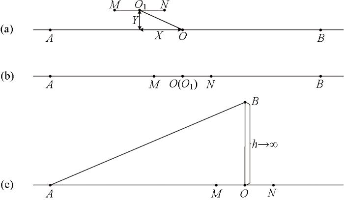
激电法勘探中常用的3种装置类型如图1 所示,其中图1 为旁侧中梯装置,O 和O 1 分别为供电导线AB 和测量导线MN 的中点,X 和Y 分别为水平方向和垂直方向上的旁侧距离;图1b 为斯伦贝谢装置,它是旁侧中梯装置中X 和Y 同时为0的一种特殊情况。由于图1 、b中均为4个电极同时供电,因此前两者被称为四极装置。而在图1c 中,供电电极B 被放置在测量电极MN 中垂线上无穷远的位置,对测量信号有影响的只有A 、M 和N 3个电极,被称为三极装置。
图1
图1
常用电极装置结构
Fig.1
Schematic of the electrode arrays in common use
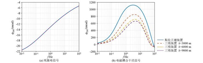
为对比不同装置在大深度激电法中的探测性能,分别计算了斯伦贝谢装置(AB =6 000 m)和三极装置(AO =3 000 m)在两层介质模型中的激电信号和电磁耦合信号。该两层介质模型中的第一层电阻率为100 Ω·m,厚度为1 000 m,第二层电阻率为10 Ω·m,厚度为无限厚。考虑到实际测量时,三极装置的供电电极B 无法真正放到无穷远的位置,其距测量点的长度h (图1c )可能会对测量结果造成影响,因此还对比了三极装置在不同h 下的测量信号,具体如图2 所示。
图2
图2
不同电极装置中激电相位和电磁耦合相位
Fig.2
The phase of IP and EM coupling in different electrode arrays
图2 展示的是不同装置参数下的纯激电相位谱,可以看到当频率极低或极高时相位较小,在中间的某个频段取得极大值,这是由不同频率下的探测深度差异引起的。当频率极低时,探测深度较大,测量信号只受第二层电阻率的影响(近似为均匀半空间),因此相位几乎为0。同样,当频率极高时,测量信号只受第一层电阻率的影响,相位值也相对较低。此外,图2 中4条激电信号曲线完全重合,说明四极装置和三极装置的探测深度都只与AO 的长度有关,从而验证了它们理论探测深度的统一性(即三极装置的探测深度d 1 ≈AO /3,对称四级的装置的探测深度d 2 ≈AB /6=AO /3)。从图2b 中可以看出不同装置参数下的电磁耦合大小是不同的,四极装置受电磁耦合干扰程度明显大于三极装置,且三极装置中h 越大,电磁耦合效应越小。因此在实际测量时,三极装置中的B 电极应放置在尽可能远的位置。
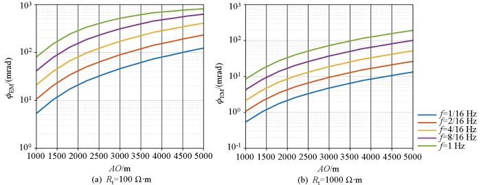
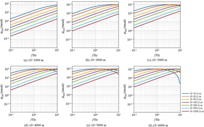
为进一步测试电磁耦合效应随供电极距和频率的变化规律,计算了不同供电极距下的三极装置在均匀半空间中电磁耦合效应。由于在三极装置中,BO >5AO 时即可认为电极B 在无穷远的位置[29 ] ,因此在下述实验中,BO 长度均被设置为15 000 m。激电法在大深度测量时,工作频率通常小于1 Hz,因此共设置了1/16 Hz、2/16 Hz、4/16 Hz、8/16 Hz和1 Hz 5个频点,具体计算结果如图3 所示。其中图3 是电阻率为100 Ω·m时的计算结果,图3b 是电阻率为1 000 Ω·m时的计算结果。通过图3 和3b对比发现,无论在低阻地层中还是在高阻地层中,电磁耦合效应随供电极距和频率的变化规律是完全一致的,即电磁耦合效应总是随着供电极距的增加而增大,随着频率的增高而变强。此外能发现在同样的供电极距和频率下,高阻层中的电磁耦合强度总是比低阻层更弱,说明电磁耦合效应随大地电阻率的升高而降低。同时也在斯伦贝谢装置中进行了同样的实验,得到的结论与三极装置中完全一致,此处不再赘述。
图3
图3
三极装置中电磁耦合效应随供电极距的变化规律
Fig.3
The variation of the EM coupling with the spacing of the current-electrodes in the pole-dipole array
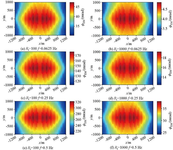
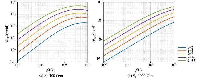
在图1 所示的旁侧中梯装置中,常通过改变旁侧距离来调整测量点位置和探测深度,因此有必要研究旁侧距离大小对电磁耦合效应的影响。图4 展示了在不同大地电阻率和频率下,电磁耦合强度随旁侧距离的变化规律。其中,x 和y 的负值分别代表测量导线MN 中点O1 在供电导线中点O的左侧和下方,反之则代表O1 在O的右侧和上方。从图中可以看出,在不同电阻率和频率下,电磁耦合强度的数值差别很大,但每一幅子图中电磁耦合强度随旁侧距离的变化规律完全一致,即旁侧距离越大,电磁耦合效应越小。此外,每幅子图均呈现中心对称性,这说明电磁耦合强度只与旁侧距离的大小有关,而与O及O1 之间的相对位置无关。不同子图中电磁耦合强度的差异再次验证了上述实验结论,即频率越高,大地电阻率越小,电磁耦合强度越大。
图4
图4
中梯装置中旁侧距离对电磁耦合强度的影响
Fig.4
Impact of side distance on EM coupling in intermediate gradient array
3 相对相位谱在不同测量装置中的去耦效果分析
常规的激电相位谱作为激电法的测量信号,在大深度勘探时极易受到电磁耦合效应的影响。前人已经验证了相对相位谱在常规深度勘探中的良好去耦效果,本章将进一步从计算原理出发,分析其适用场景,并定量考察其在大深度激电勘探中的应用效果。
3.1 相对相位谱计算原理
(7) ${\varphi }_{r}\left(f\right)=\frac{k·\varphi \left(f\right)-\varphi (k·f)}{k-1}$
式中:ϕr (f )和ϕ (f )分别是频率为f 时的相位和相对相位;k 为相对相位法中的频比,一般来说,k 越大,激电相位谱和相对相位谱的差异越小[19 ] 。
相位谱由激电信号和电磁耦合效应两部分组成,二者的频率特性有很大差异,在一定频率范围内近似满足式(8):
(8) $\begin{array}{l}\varphi ={\varphi }_{EM}+{\varphi }_{IP},\\ {\varphi }_{EM}(k·f)\approx k·{\varphi }_{EM}\left(f\right),\\ {\varphi }_{IP}(k·f)\approx {\varphi }_{IP}\left(f\right)\end{array}$。
将式(8)代入式(7)可将相对相位谱的计算公式进一步推导为式(9),可以发现最终得到的相对相位ϕr 与激电相位ϕ IP 近似相等,从而消除了电磁耦合效应ϕ EM 的影响。
(9) $\begin{array}{l}{\varphi }_{r}\left(f\right)=\\ \frac{k·{\varphi }_{EM}\left(f\right)+k·{\varphi }_{IP}\left(f\right)-{\varphi }_{EM}(k·f)-{\varphi }_{IP}(k·f)}{k-1}\approx \\ \frac{(k-1){\varphi }_{IP}\left(f\right)}{k-1}={\varphi }_{IP}\left(f\right)\end{array}$。
从上述公式的推导可以发现,相对相位法的去耦效果主要取决于式(8)中“≈”两侧数值之间的差异。当两侧数值完全相等时,电磁耦合的影响能够完全消除;反之,二者之间的差异越大,相对相位谱计算过程中引入的误差也越大,从而影响去耦效果。为了定性的分析相对相位法的应用场景,计算了斯伦贝谢装置在不同电阻率下的频率特性,结果如图5 所示。可以看到图5 中由于供电极距较小,几乎所有曲线都呈现良好的线性关系,说明相对相位谱在常规勘探深度中具有良好的去耦效果。然而,随着供电极距(勘探深度)的增大,低阻和高频段的曲线形态不再满足式(8)所述的线性关系,且供电极距越大,电磁耦合效应与频率之间的线性关系越差,表明相对相位谱在长极距、高频和低阻条件下的去耦效果较差。
图5
图5
斯伦贝谢装置中电磁耦合响应频率特性
Fig.5
The frequency response characteristics of EM coupling in Schlumberger array
3.2 相对相位法在不同装置类型中的去耦效果
在长极距、低阻和高频情况下,相对相位法难以完全去除电磁耦合效应,此时式(8)中的ϕr ≈ϕ IP 不再成立,而是也包含了一部分电磁耦合干扰,即ϕr =ϕ IP +ϕ EM 。因此,可以通过计算不同装置类型、频率和大地电阻率下的ϕ EM 分量,从而定量分析相对相位法在大深度(主要针对1 000 m的勘探深度)激电法中的应用效果。
首先基于斯伦贝谢装置(AB =6 000 m)考察了相对相位法中频比对去耦效果的影响。大地电阻率和频比不同时,电磁耦合ϕ EM 大小随频率的变化规律如图6 所示,其中图6 是电阻率为100 Ω·m时的计算结果,图6b 是电阻率为1 000 Ω·m时的计算结果。可以发现,在相同频率条件下,无论是在低阻层还是高阻层中,电磁耦合效应均随着频比的增大而增强,当频比设置为2时有着最佳去耦效果。然而,即使如此,随着频率的升高或电阻率的降低,由于电磁干扰强度的增加,相对相位中的电磁耦合分量也迅速增大。这说明,利用相对相位法只能去除一部分电磁耦合干扰。
图6
图6
相对相位法中频比对去耦效果的影响
Fig.6
The impact of frequency ratio on decoupling effect in the relative phase method
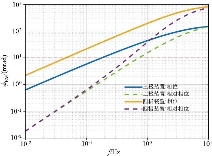
为分析相对相位法在不同测量装置中的去耦效果,首先基于均匀半空间(R t =350 Ω·m)地层计算了三极装置(AO =3 000 m)和四极装置(AB =6 000 m)常规激电相位谱中的电磁耦合分量,如图7 中的两条实线所示。然后将频比设置为2,计算相对相位谱中的电磁耦合分量,如图7 中的两条虚线所示。对同一测量装置而言,在低频段激电相位谱中的电磁耦合效应总是强于相对相位谱,说明相对相位法能够去除一部分耦合干扰。然而,随着频率的增高,激电相位谱和相对相位谱之间的差异逐渐减小,说明相对相位法的去耦效果随着频率的升高而变差,尤其是当频率增加到10 Hz时,相位和相对相位几乎相等,说明此时由于式(8)中“≈”两侧数值之间的差异过大,导致相对相位法不再具有去耦能力。此外,在同一频率下,三极装置测量的激电相位或相对相位中的电磁耦合分量均小于四极装置,再次验证了在相同的勘探深度下,三极装置受电磁耦合干扰程度更小。
图7
图7
不同测量装置的激电相位谱和相对相位谱对比
Fig.7
Comparison of IP phase and relative phase in different electrode arrays
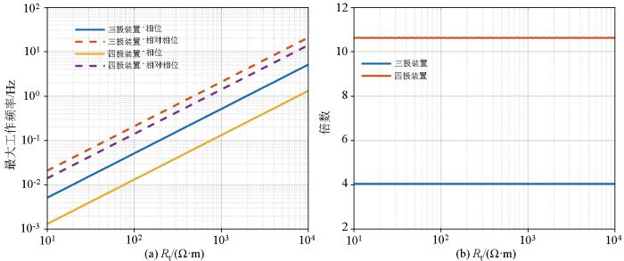
从图7 中能够看出,激电相位谱和相对相位谱中的电磁耦合分量随着频率的升高而增大,当其大于10 mrad(图7 中红色虚线所示)时,则认为激电信号被严重干扰。因此可以基于这个指标确定三极装置和四极装置采用激电相位以及相对相位作为探测信号时的最大工作频率,从而定量分析相对相位法在不同测量装置中的去耦效果。
针对1 000 m的探测深度,将三极装置的供电极距AO 设置为3 000 m,斯伦贝谢装置的供电极距AB 设置为6 000 m,分别计算它们在不同电阻率下的最大工作频率,结果如图8 所示。可以看到,随着大地电阻率的增加,由于电磁耦合干扰强度的降低,常规的激电相位谱法和相对相位谱法的最大工作频率都在线性变大。利用激电相位谱测量时,三极装置的最大工作频率明显大于四极装置,而采用相对相位谱进行测量时,虽然三极装置的最大工作频率依然大于四极装置,但二者之间的差距变得更小,说明相对相位法在不同测量装置中的去耦效果是不同的。图8b 进一步展示了相对相位谱的去耦效果,可以看到三极装置在采用相对相位谱后,最大工作频率提升了4倍,而四极装置则提升了近11倍,且最大工作频率提升的倍数均为常数,不随大地电阻率的变化而变化。通过将激电相位谱和相对相位谱的最大工作频率作对比,证明相对相位法在大深度激电法中也有一定的去耦效果。
图8
图8
激电相位谱和相对相位谱的最大工作频率对比
Fig.8
Comparison of the maximum working frequency of IP phase and relative phase
3.3 相对相位法去耦案例
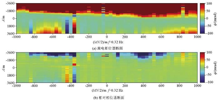
为了验证相对相位法去除电磁耦合干扰的有效性,本文对阿拉善呼和沙拉某矿区的扩频激电测量数据进行了分析。数据采集时使用三极装置,供电电极(A )数量为66个,分布在-3 600~3 600 m的测线上,测量电极共有51对,均匀分布在-1 000~1 000 m的位置上。通过对所有测量数据进行处理,形成如图9 所示的两个断面,分别为激电相位谱断面(图9 )和相对相位谱断面(图9b )。从图9 中可以看出常规的激电相位谱受到了严重的电磁耦合干扰,导致相位谱图中出现了严重的噪声和伪影,无法区分出激电异常信号,导致无法识别出潜在的异常区域。采用相对相位法后,图9b 中的电磁耦合干扰显著减少,激电异常信号的识别变得更加清晰,在测线-700~-500 m、300~500 m的区域内出现了明显的激电异常。通过对比两幅图像可以发现,相对相位法能够有效去除电磁耦合的影响,显著提高了激电异常识别的准确性。因此,基于相对相位法的去耦技术在扩频激电测量中的应用具有重要的实际意义。
图9
图9
相对相位法去耦效果(以呼和沙拉某矿区为例)
Fig.9
The decoupling effect of the relative phase method (a case study of the Huhe-shala mining area)
4 结论
1)三极装置和对称四级装置的理论探测深度只与AO 的长度有关,在AO 长度相同时,两种测量装置测得的纯激电信号是完全一样的,而主要区别在于在相同的探测条件下,四极装置受电磁耦合干扰程度总是强于三极装置。
2)三极装置和四极装置中的电磁耦合强度主要受到工作频率、供电极距和大地电阻率的影响,其中大地电阻率越小、电极距越长、工作频率越高,电磁耦合强度越大。此外,旁侧中梯装置的电磁耦合强度还受到旁侧距离的影响,旁侧距离越小,电磁耦合强度越大,当垂直旁侧距离和水平旁侧距离均为0时,电磁耦合强度最大。三极装置中的电磁耦合强度还受到OB 距离的影响,即B 点放置的越远,电磁耦合效应越小,因此在实际施工时,电极B 应放置的尽可能远。
3)由于相对相位法中假设的条件,即k ·ϕ EM (f )≈ϕ EM (k ·f )并不总是满足,特别是在长极距、高频、低阻情况下,因此其去耦效果及应用场景是有限的。针对1 000 m的探测深度,相对相位谱的引入可将对称四极装置和三极装置的最大工作频率分别提高10.6倍和4倍。
参考文献
View Option
[1]
滕吉文 , 杨立强 , 姚敬全 , 等 . 金属矿产资源的深部找矿、勘探与成矿的深层动力过程
[J]. 地球物理学进展 , 2007 , 22 (2 ):317 -334 .
[本文引用: 1]
Teng J W Yang L Q Yao J Q et al. Deep disscover ore exploration and exploitation for metal mineral resocrces and its deep dynamical process of formation
[J]. Progress in Geophysics , 2007 , 22 (2 ):317 -334 .
[本文引用: 1]
[2]
严加永 , 滕吉文 , 吕庆田 . 深部金属矿产资源地球物理勘查与应用
[J]. 地球物理学进展 , 2008 , 23 (3 ):871 -891 .
Yan J Y Teng J W Lyu Q T Geophysical exploration and application of deep metallic ore resources
[J]. Progress in Geophysics , 2008 , 23 (3 ):871 -891 .
[3]
李鹏 , 罗玉钦 , 田有 , 等 . 深部地质资源地球物理探测技术研究发展
[J]. 地球物理学进展 , 2021 , 36 (5 ):2011 -2033 .
[本文引用: 1]
Li P Luo Y Q Tian Y et al. Research progress of geophysical exploration technology for deep geological resources
[J]. Progress in Geophysics , 2021 , 36 (5 ):2011 -2033 .
[本文引用: 1]
[4]
Davydycheva S Rykhlinski N Legeido P Electrical-prospecting method for hydrocarbon search using the induced-polarization effect
[J]. Geophysics , 2006 , 71 (4 ):G179-G189.
[本文引用: 1]
[5]
Veeken P C Legeydo P J Davidenko Y A et al. Benefits of the induced polarization geoelectric method to hydrocarbon exploration
[J]. Geophysics , 2009 , 74 (2 ):B47-B59.
[6]
Schleifer N Weller A Schneider S et al. Investigation of a Bronze Age plankway by spectral induced polarization
[J]. Archaeological Prospection . 2002 , 9 :243 -25 .
DOI:10.1002/arp.v9:4
URL
[7]
Gazoty A Fiandaca G Pedersen J et al. Application of time domain induced polarization to the mapping of lithotypes in a landfill site
[J]. Hydrology and Earth System Sciences , 2012 , 16 (6 ):1793 -1804 .
DOI:10.5194/hess-16-1793-2012
URL
[本文引用: 1]
. A direct current (DC) resistivity and time domain induced polarization (TDIP) survey was undertaken at a decommissioned landfill site situated in Hørløkke, Denmark, for the purpose of mapping the waste deposits and to discriminate important geological units that control the hydrology of the surrounding area. It is known that both waste deposits and clay have clear signatures in TDIP data, making it possible to enhance the resolution of geological structures compared to DC surveys alone. Four DC/TDIP profiles were carried out crossing the landfill, and another seven profiles in the surroundings provide a sufficiently dense coverage of the entire area. The whole dataset was inverted using a 1-D laterally constrained inversion scheme, recently implemented for TDIP data, in order to use the entire decay curves for reconstructing the electrical parameters of the soil in terms of the Cole-Cole polarization model. Results show that it is possible to resolve both the geometry of the buried waste body and key geological structures. In particular, it was possible to find a silt/clay lens at depth that correlates with the flow direction of the pollution plume spreading out from the landfill and to map a shallow sandy layer rich in clay that likely has a strong influence on the hydrology of the site. This interpretation of the geophysical findings was constrained by borehole data, in terms of geology and gamma ray logging. The results of this study are important for the impact of the resolved geological units on the hydrology of the area, making it possible to construct more realistic scenarios of the variation of the pollution plume as a function of the climate change.
[8]
Routh P S Oldenburg D W Electromagnetic coupling in frequency-domain induced polarization data:A method for removal
[J]. Geophysical Journal International , 2001 , 145 (1 ):59 -76 .
DOI:10.1111/gji.2001.145.issue-1
URL
[本文引用: 1]
[9]
Wang J Zhan K Shien L et al. Fundamental characteristics of an approximate correction method for electromagnetic coupling in frequency-domain induced polarization
[J]. Geophysics , 1985 , 50 (2 ):235 -241 .
DOI:10.1190/1.1441913
URL
[本文引用: 1]
Our studies have determined that both gradient and dipole-dipole arrays may produce a rather strong electromagnetic (EM) coupling effect under certain conditions. Variations in these apparent effects are closely correlated with changes of surface current density and also influenced by topographic relief. The dipole-dipole array can provide EM coupling anomalies with the same sign and shape as bona fide induced-polarization (IP) anomalies.It has been shown by theoretical calculations and model studies that response curves of frequency effects of EM coupling in logarithmic coordinates have distinctive features of sectional linearization. This can provide a basic method to correct approximately EM coupling. Compared with methods being used inside and outside China, the suggested correction method has the advantage of wide application. This has been already proven by a few field examples.
[10]
陈儒军 , 罗维炳 , 何继善 , 等 . 高精度多频电法数据采集系统
[J]. 物探与化探 , 2003 , 27 (5 ):375 -378 .
[本文引用: 1]
Chen R J Luo W B He J S et al. The data acquisition system in the high-precision multi frequency electric method
[J]. Geophysical and Geochemical Exploration , 2003 , 27 (5 ):375 -378 .
[本文引用: 1]
[11]
肖都 , 郭鹏 , 林品荣 , 等 . 相位激电法在强干扰区的应用试验
[J]. 物探化探计算技术 , 2016 , 38 (5 ):593 -597 .
Xiao D Guo P Lin P R et al. Phase-IP experimental effects under the condition of strong interference and difficult grounding
[J]. Computing Techniques for Geophysical and Geochemical Exploration , 2016 , 38 (5 ):593 -597 .
[12]
付国红 , 潘志 , 程辉 , 等 . 频率域激电发送端去耦建模与仿真分析
[J]. 地球物理学进展 , 2016 , 31 (4 ):1569 -1574 .
Fu G H Pan Z Cheng H et al. Decoupling model and simulation analysis from signal transmitters in frequency domain IP
[J]. Progress in Geophysics , 2016 , 31 (4 ):1569 -1574 .
[13]
冉军林 , 刘俊岩 . 组合激电测深装置的应用与研究
[J]. 物探与化探 , 2018 , 42 (6 ):1259 -1263 .
[本文引用: 1]
Ran J L Liu J Y The application and study of induced polarization group device
[J]. Geophysical and Geochemical Exploration , 2018 , 42 (6 ):1259 -1263 .
[本文引用: 1]
[14]
黄寄洲 , 张国鸿 . 频率域激电法的电磁耦合校正应用研究
[J]. 安徽地质 , 2014 , 24 (3 ):205 -209 .
[本文引用: 1]
Huang J Z Zhang G H Applied research of electromagnetic coupling correction in frequency domain IP
[J]. Geology of Anhui , 2014 , 24 (3 ):205 -209 .
[本文引用: 1]
[15]
徐勇 , 陈林 , 管文慧 . 变频法电磁耦合效应校正原理与实例
[J]. 西部资源 , 2012 ,(4 ):190 -191 .
Xu Y Chen L Guan W H The correction principle and examples of electromagnetic coupling effect in frequency conversion method
[J]. Western Resources , 2012 ,(4 ):190 -191 .
[16]
崔燕丽 , 白宜诚 , 罗维斌 . 多频去耦在双频激电数据去耦中的应用
[J]. 物探与化探 , 2006 , 30 (1 ):71 -74 .
[本文引用: 1]
Cui Y L Bai Y C Luo W B The application of multiple frequency decoupling method to the removal of dual-frequency IP coupling effect
[J]. Geophysical and Geochemical Exploration , 2006 , 30 (1 ):71 -74 .
[本文引用: 1]
[17]
郭鹏 . 中梯装置相位激电电磁耦合研究
[J]. 物探化探计算技术 , 2015 , 37 (1 ):22 -26 .
[本文引用: 1]
Guo P A study on electromagnetic coupling of central gradient array phase-IP
[J]. Computing Techniques for Geophysical and Geochemical Exploration , 2015 , 37 (1 ):22 -26 .
[本文引用: 1]
[18]
郭鹏 , 林品荣 , 石福升 . 相位激电电磁耦合两频校正技术
[J]. 物探与化探 , 2010 , 34 (4 ):489 -492 .
[本文引用: 1]
Guo P Lin P R Shi F S The phase-IP electromagnetic coupling correction technique of two frequencies
[J]. Geophysical and Geochemical Exploration , 2010 , 34 (4 ):489 -492 .
[本文引用: 1]
[19]
陈儒军 , 何继善 , 白宜诚 , 等 . 多频激电相对相位谱研究
[J]. 中南大学学报:自然科学版 , 2004 , 35 (1 ):106 -111 .
[本文引用: 2]
Chen R J He J S Bai Y C et al. The study of relative phase spectrum in multi-frequency induced polarization
[J]. Journal of Central South University of Technology:Natural Science Edition , 2004 , 35 (1 ):106 -111 .
[本文引用: 2]
[20]
李栋 , 杨帆 , 高鹏举 . 相位激电法电磁耦合效应的校正
[J]. 矿产勘查 , 2019 , 10 (2 ):316 -320 .
[本文引用: 1]
Li D Yang F Gao P J The Phase-IP electromagnetic coupling correction
[J]. Mineral Exploration , 2019 , 10 (2 ):316 -320 .
[本文引用: 1]
[21]
向毕文 , 陈儒军 , 淳少恒 , 等 . 利用指数函数拟合去除扩频激电信号中的电磁耦合感应
[J]. 物探与化探 , 2015 , 39 (5 ):1053 -1058 .
[本文引用: 1]
Xiang B W Chen R J Chun S H et al. A new method for removing EM-coupling in spread spectrum induced polarization based on exponential function fitting
[J]. Geophysical and Geochemical Exploration , 2015 , 39 (5 ):1053 -1058 .
[本文引用: 1]
[22]
Thomas I N Francois B CRID mod:A matlab program to model ID complex resisivity effects in electrical and electromagnetic surveys
[J]. Computer & Geosciences , 2006 , 32 (9 ):1411 -1419 .
DOI:10.1016/j.cageo.2006.01.001
URL
[本文引用: 1]
[23]
Madden T R Cantwell T Induced polarization,a review
[C]// Society of Exploration Geophysicists , 1967 .
[本文引用: 1]
[24]
Sunde E D Earth conduction effects in transmission system [M]. New York : Dover , 1968 .
[本文引用: 1]
[25]
Dey A Morrison H F Electromagnetic coupling in frequency and time-domain induced-polarization surveys over a multilayered earth
[J]. Geophysics , 1973 , 38 :380 -405 .
DOI:10.1190/1.1440348
URL
[本文引用: 1]
Electromagnetic coupling responses in frequency and time-domain induced-polarization measurements over a multilayered earth are evaluated. For collinear dipole-dipole and pole-dipole configurations over a dissipative layered subsurface, the percent frequency effects of electromagnetic coupling are seen to be as high as 60 percent for large L2(σ1f) values, where L is the length of the receiving dipole, σ1 is the conductivity of the top layer of the half-space, and f is the higher frequency of excitation used. In both frequency and time-domain analyses, the distinctive effects of layering compared to that of a homogeneous half-pace response are shown for different electrode configurations, layer geometry, and electrical parameters of the subsurface. The pole-dipole configuration of electrodes, in general, exhibits higher coupling compared to the dipole-dipole configuration. In time-domain measurements, the late off-time transient decays reflect almost entirely the normal polarizability of the layered subsurface, in that the coupling responses are significant only during the early off-time of the transient.
[26]
于立波 . 一维频谱激电法正反演研究 [D]. 长春 : 吉林大学 , 2010 .
[本文引用: 1]
Yu L B The study of simulation and inversion of 1D spectrum induced polarization method [D]. Changchun : Jilin University , 2010 .
[本文引用: 1]
[27]
刘飞 . 含电磁耦合效应的频谱激电一维正反演 [D]. 抚州 : 东华理工大学 , 2014 .
[本文引用: 1]
Liu F One-dimensional forward and backward modeling of spectrum induced polarization with electromagnetic coupling effect [D]. Fuzhou : East China Institute of Technology , 2014 .
[本文引用: 1]
[28]
Ghorbani A Camerlynck C Florsch N CR1Dinv:A Matlab program to invert 1D spectral induced polarization data for the Cole-Cole model including electromagnetic effects
[J]. Computers & Geosciences , 2009 , 35 (2 ):255 -266 .
DOI:10.1016/j.cageo.2008.06.001
URL
[29]
牛超 , 施龙青 , 肖乐乐 , 等 . 非无穷远极距对三极直流电法影响
[J]. 地球物理学进展 , 2013 , 28 (6 ):3324 -3331 .
[本文引用: 2]
Niu C Shi L Q Xiao L L et al. Influence of pole-dipole array electric sounding under non-infinite space
[J]. Progress in Geophysics , 2013 , 28 (6 ):3324 -3331 .
[本文引用: 2]
金属矿产资源的深部找矿、勘探与成矿的深层动力过程
1
2007
... 丰富的矿产资源是现代工业和经济快速发展的重要前提,随着浅层矿产资源的逐渐减少,对深部金属矿勘探提出了更高的要求[1 3 ] .激电法作为一种多功能的地球物理勘探方法,在了解地质结构、寻找地下水和金属矿勘探中有着非常广泛的应用[4 7 ] .然而,该方法在进行频散率和相位测量时容易受到电磁耦合的影响,特别是在大深度或低阻勘探过程中,电磁耦合效应更加强烈,从而对激电信号造成严重干扰[8 -9 ] . ...
金属矿产资源的深部找矿、勘探与成矿的深层动力过程
1
2007
... 丰富的矿产资源是现代工业和经济快速发展的重要前提,随着浅层矿产资源的逐渐减少,对深部金属矿勘探提出了更高的要求[1 3 ] .激电法作为一种多功能的地球物理勘探方法,在了解地质结构、寻找地下水和金属矿勘探中有着非常广泛的应用[4 7 ] .然而,该方法在进行频散率和相位测量时容易受到电磁耦合的影响,特别是在大深度或低阻勘探过程中,电磁耦合效应更加强烈,从而对激电信号造成严重干扰[8 -9 ] . ...
深部地质资源地球物理探测技术研究发展
1
2021
... 丰富的矿产资源是现代工业和经济快速发展的重要前提,随着浅层矿产资源的逐渐减少,对深部金属矿勘探提出了更高的要求[1 3 ] .激电法作为一种多功能的地球物理勘探方法,在了解地质结构、寻找地下水和金属矿勘探中有着非常广泛的应用[4 7 ] .然而,该方法在进行频散率和相位测量时容易受到电磁耦合的影响,特别是在大深度或低阻勘探过程中,电磁耦合效应更加强烈,从而对激电信号造成严重干扰[8 -9 ] . ...
深部地质资源地球物理探测技术研究发展
1
2021
... 丰富的矿产资源是现代工业和经济快速发展的重要前提,随着浅层矿产资源的逐渐减少,对深部金属矿勘探提出了更高的要求[1 3 ] .激电法作为一种多功能的地球物理勘探方法,在了解地质结构、寻找地下水和金属矿勘探中有着非常广泛的应用[4 7 ] .然而,该方法在进行频散率和相位测量时容易受到电磁耦合的影响,特别是在大深度或低阻勘探过程中,电磁耦合效应更加强烈,从而对激电信号造成严重干扰[8 -9 ] . ...
Electrical-prospecting method for hydrocarbon search using the induced-polarization effect
1
2006
... 丰富的矿产资源是现代工业和经济快速发展的重要前提,随着浅层矿产资源的逐渐减少,对深部金属矿勘探提出了更高的要求[1 3 ] .激电法作为一种多功能的地球物理勘探方法,在了解地质结构、寻找地下水和金属矿勘探中有着非常广泛的应用[4 7 ] .然而,该方法在进行频散率和相位测量时容易受到电磁耦合的影响,特别是在大深度或低阻勘探过程中,电磁耦合效应更加强烈,从而对激电信号造成严重干扰[8 -9 ] . ...
Benefits of the induced polarization geoelectric method to hydrocarbon exploration
0
2009
Investigation of a Bronze Age plankway by spectral induced polarization
0
2002
Application of time domain induced polarization to the mapping of lithotypes in a landfill site
1
2012
... 丰富的矿产资源是现代工业和经济快速发展的重要前提,随着浅层矿产资源的逐渐减少,对深部金属矿勘探提出了更高的要求[1 3 ] .激电法作为一种多功能的地球物理勘探方法,在了解地质结构、寻找地下水和金属矿勘探中有着非常广泛的应用[4 7 ] .然而,该方法在进行频散率和相位测量时容易受到电磁耦合的影响,特别是在大深度或低阻勘探过程中,电磁耦合效应更加强烈,从而对激电信号造成严重干扰[8 -9 ] . ...
Electromagnetic coupling in frequency-domain induced polarization data:A method for removal
1
2001
... 丰富的矿产资源是现代工业和经济快速发展的重要前提,随着浅层矿产资源的逐渐减少,对深部金属矿勘探提出了更高的要求[1 3 ] .激电法作为一种多功能的地球物理勘探方法,在了解地质结构、寻找地下水和金属矿勘探中有着非常广泛的应用[4 7 ] .然而,该方法在进行频散率和相位测量时容易受到电磁耦合的影响,特别是在大深度或低阻勘探过程中,电磁耦合效应更加强烈,从而对激电信号造成严重干扰[8 -9 ] . ...
Fundamental characteristics of an approximate correction method for electromagnetic coupling in frequency-domain induced polarization
1
1985
... 丰富的矿产资源是现代工业和经济快速发展的重要前提,随着浅层矿产资源的逐渐减少,对深部金属矿勘探提出了更高的要求[1 3 ] .激电法作为一种多功能的地球物理勘探方法,在了解地质结构、寻找地下水和金属矿勘探中有着非常广泛的应用[4 7 ] .然而,该方法在进行频散率和相位测量时容易受到电磁耦合的影响,特别是在大深度或低阻勘探过程中,电磁耦合效应更加强烈,从而对激电信号造成严重干扰[8 -9 ] . ...
高精度多频电法数据采集系统
1
2003
... 上述问题可以从硬件采集端和数据处理两个方面来解决.前者可通过增大发射电流提高数据采集信噪比,再经选频接收、相干检测等手段增强接收机抗干扰能力[10 13 ] .后者主要是利用去耦方法对测量信号进行后处理,从而消除电磁耦合效应的影响,前人已经在这方面做了大量的工作,可总结分为3大类: ...
高精度多频电法数据采集系统
1
2003
... 上述问题可以从硬件采集端和数据处理两个方面来解决.前者可通过增大发射电流提高数据采集信噪比,再经选频接收、相干检测等手段增强接收机抗干扰能力[10 13 ] .后者主要是利用去耦方法对测量信号进行后处理,从而消除电磁耦合效应的影响,前人已经在这方面做了大量的工作,可总结分为3大类: ...
组合激电测深装置的应用与研究
1
2018
... 上述问题可以从硬件采集端和数据处理两个方面来解决.前者可通过增大发射电流提高数据采集信噪比,再经选频接收、相干检测等手段增强接收机抗干扰能力[10 13 ] .后者主要是利用去耦方法对测量信号进行后处理,从而消除电磁耦合效应的影响,前人已经在这方面做了大量的工作,可总结分为3大类: ...
组合激电测深装置的应用与研究
1
2018
... 上述问题可以从硬件采集端和数据处理两个方面来解决.前者可通过增大发射电流提高数据采集信噪比,再经选频接收、相干检测等手段增强接收机抗干扰能力[10 13 ] .后者主要是利用去耦方法对测量信号进行后处理,从而消除电磁耦合效应的影响,前人已经在这方面做了大量的工作,可总结分为3大类: ...
频率域激电法的电磁耦合校正应用研究
1
2014
... 第一类是假设频率域激电效应的振幅随频率对数近似线性增加,而电磁耦合的振幅则随频率呈指数增加,从而可以通过两频校正方法去除电磁耦合效应[14 16 ] .例如,郭鹏等[17 -18 ] 研究了中梯装置中电磁耦合效应的影响因素和频率特征,并利用两频校正方法消除了电磁耦合的影响.第二类是假设低频段激电效应的相位随频率变化不大,而电磁耦合引起的相位则随频率线性增大,从而可利用相对相位法进行线性校正.例如,陈儒军等[19 ] 基于这一特性推导了相对相位谱的计算公式,并通过实验证明相对相位谱测量不仅能有效抑制电磁耦合感应,还能消除由于发送机与接收机之间同步误差造成的影响.李栋等[20 ] 研究了偶极装置中的电磁耦合响应,并将相对相位法应用于实测激电资料的处理中,进一步验证了该去耦方法的有效性.第三类是根据电磁耦合效应和激电效应在时间域的差异进行斩波去耦.例如,向毕文等[21 ] 利用指数函数在时间域内对激电效应进行拟合,从而在保留激电信号的同时去除了电磁耦合效应,取得了良好的效果. ...
多频去耦在双频激电数据去耦中的应用
1
2006
... 第一类是假设频率域激电效应的振幅随频率对数近似线性增加,而电磁耦合的振幅则随频率呈指数增加,从而可以通过两频校正方法去除电磁耦合效应[14 16 ] .例如,郭鹏等[17 -18 ] 研究了中梯装置中电磁耦合效应的影响因素和频率特征,并利用两频校正方法消除了电磁耦合的影响.第二类是假设低频段激电效应的相位随频率变化不大,而电磁耦合引起的相位则随频率线性增大,从而可利用相对相位法进行线性校正.例如,陈儒军等[19 ] 基于这一特性推导了相对相位谱的计算公式,并通过实验证明相对相位谱测量不仅能有效抑制电磁耦合感应,还能消除由于发送机与接收机之间同步误差造成的影响.李栋等[20 ] 研究了偶极装置中的电磁耦合响应,并将相对相位法应用于实测激电资料的处理中,进一步验证了该去耦方法的有效性.第三类是根据电磁耦合效应和激电效应在时间域的差异进行斩波去耦.例如,向毕文等[21 ] 利用指数函数在时间域内对激电效应进行拟合,从而在保留激电信号的同时去除了电磁耦合效应,取得了良好的效果. ...
中梯装置相位激电电磁耦合研究
1
2015
... 第一类是假设频率域激电效应的振幅随频率对数近似线性增加,而电磁耦合的振幅则随频率呈指数增加,从而可以通过两频校正方法去除电磁耦合效应[14 16 ] .例如,郭鹏等[17 -18 ] 研究了中梯装置中电磁耦合效应的影响因素和频率特征,并利用两频校正方法消除了电磁耦合的影响.第二类是假设低频段激电效应的相位随频率变化不大,而电磁耦合引起的相位则随频率线性增大,从而可利用相对相位法进行线性校正.例如,陈儒军等[19 ] 基于这一特性推导了相对相位谱的计算公式,并通过实验证明相对相位谱测量不仅能有效抑制电磁耦合感应,还能消除由于发送机与接收机之间同步误差造成的影响.李栋等[20 ] 研究了偶极装置中的电磁耦合响应,并将相对相位法应用于实测激电资料的处理中,进一步验证了该去耦方法的有效性.第三类是根据电磁耦合效应和激电效应在时间域的差异进行斩波去耦.例如,向毕文等[21 ] 利用指数函数在时间域内对激电效应进行拟合,从而在保留激电信号的同时去除了电磁耦合效应,取得了良好的效果. ...
相位激电电磁耦合两频校正技术
1
2010
... 第一类是假设频率域激电效应的振幅随频率对数近似线性增加,而电磁耦合的振幅则随频率呈指数增加,从而可以通过两频校正方法去除电磁耦合效应[14 16 ] .例如,郭鹏等[17 -18 ] 研究了中梯装置中电磁耦合效应的影响因素和频率特征,并利用两频校正方法消除了电磁耦合的影响.第二类是假设低频段激电效应的相位随频率变化不大,而电磁耦合引起的相位则随频率线性增大,从而可利用相对相位法进行线性校正.例如,陈儒军等[19 ] 基于这一特性推导了相对相位谱的计算公式,并通过实验证明相对相位谱测量不仅能有效抑制电磁耦合感应,还能消除由于发送机与接收机之间同步误差造成的影响.李栋等[20 ] 研究了偶极装置中的电磁耦合响应,并将相对相位法应用于实测激电资料的处理中,进一步验证了该去耦方法的有效性.第三类是根据电磁耦合效应和激电效应在时间域的差异进行斩波去耦.例如,向毕文等[21 ] 利用指数函数在时间域内对激电效应进行拟合,从而在保留激电信号的同时去除了电磁耦合效应,取得了良好的效果. ...
多频激电相对相位谱研究
2
2004
... 第一类是假设频率域激电效应的振幅随频率对数近似线性增加,而电磁耦合的振幅则随频率呈指数增加,从而可以通过两频校正方法去除电磁耦合效应[14 16 ] .例如,郭鹏等[17 -18 ] 研究了中梯装置中电磁耦合效应的影响因素和频率特征,并利用两频校正方法消除了电磁耦合的影响.第二类是假设低频段激电效应的相位随频率变化不大,而电磁耦合引起的相位则随频率线性增大,从而可利用相对相位法进行线性校正.例如,陈儒军等[19 ] 基于这一特性推导了相对相位谱的计算公式,并通过实验证明相对相位谱测量不仅能有效抑制电磁耦合感应,还能消除由于发送机与接收机之间同步误差造成的影响.李栋等[20 ] 研究了偶极装置中的电磁耦合响应,并将相对相位法应用于实测激电资料的处理中,进一步验证了该去耦方法的有效性.第三类是根据电磁耦合效应和激电效应在时间域的差异进行斩波去耦.例如,向毕文等[21 ] 利用指数函数在时间域内对激电效应进行拟合,从而在保留激电信号的同时去除了电磁耦合效应,取得了良好的效果. ...
... 式中:ϕr (f )和ϕ (f )分别是频率为f 时的相位和相对相位;k 为相对相位法中的频比,一般来说,k 越大,激电相位谱和相对相位谱的差异越小[19 ] . ...
相位激电法电磁耦合效应的校正
1
2019
... 第一类是假设频率域激电效应的振幅随频率对数近似线性增加,而电磁耦合的振幅则随频率呈指数增加,从而可以通过两频校正方法去除电磁耦合效应[14 16 ] .例如,郭鹏等[17 -18 ] 研究了中梯装置中电磁耦合效应的影响因素和频率特征,并利用两频校正方法消除了电磁耦合的影响.第二类是假设低频段激电效应的相位随频率变化不大,而电磁耦合引起的相位则随频率线性增大,从而可利用相对相位法进行线性校正.例如,陈儒军等[19 ] 基于这一特性推导了相对相位谱的计算公式,并通过实验证明相对相位谱测量不仅能有效抑制电磁耦合感应,还能消除由于发送机与接收机之间同步误差造成的影响.李栋等[20 ] 研究了偶极装置中的电磁耦合响应,并将相对相位法应用于实测激电资料的处理中,进一步验证了该去耦方法的有效性.第三类是根据电磁耦合效应和激电效应在时间域的差异进行斩波去耦.例如,向毕文等[21 ] 利用指数函数在时间域内对激电效应进行拟合,从而在保留激电信号的同时去除了电磁耦合效应,取得了良好的效果. ...
利用指数函数拟合去除扩频激电信号中的电磁耦合感应
1
2015
... 第一类是假设频率域激电效应的振幅随频率对数近似线性增加,而电磁耦合的振幅则随频率呈指数增加,从而可以通过两频校正方法去除电磁耦合效应[14 16 ] .例如,郭鹏等[17 -18 ] 研究了中梯装置中电磁耦合效应的影响因素和频率特征,并利用两频校正方法消除了电磁耦合的影响.第二类是假设低频段激电效应的相位随频率变化不大,而电磁耦合引起的相位则随频率线性增大,从而可利用相对相位法进行线性校正.例如,陈儒军等[19 ] 基于这一特性推导了相对相位谱的计算公式,并通过实验证明相对相位谱测量不仅能有效抑制电磁耦合感应,还能消除由于发送机与接收机之间同步误差造成的影响.李栋等[20 ] 研究了偶极装置中的电磁耦合响应,并将相对相位法应用于实测激电资料的处理中,进一步验证了该去耦方法的有效性.第三类是根据电磁耦合效应和激电效应在时间域的差异进行斩波去耦.例如,向毕文等[21 ] 利用指数函数在时间域内对激电效应进行拟合,从而在保留激电信号的同时去除了电磁耦合效应,取得了良好的效果. ...
CRID mod:A matlab program to model ID complex resisivity effects in electrical and electromagnetic surveys
1
2006
... 上述研究成果对激电信号的高质量提取有着重要的意义,但他们的研究对象均为浅层矿体,没有考虑在深部勘探中电磁耦合对激电信号的影响.在大深度勘探中,由于供电极距的增加导致电磁耦合强度增大,测量信号也会变得更加复杂,上述方法假设的有效性需要进一步的验证.为此,本文基于Thomas等[22 ] 发布的CR1Dmod开源程序对大深度激电中的电磁耦合效应进行研究,分析装置类型、布线方式、大地电阻率阻值和频率等因素对电磁耦合强度的影响.同时从相对相位谱的计算原理出发,分析其在处理大深度激电数据的适用性,并定量考察其在三极装置和四极装置中的去耦效果,得到的结论对大深度激电找矿的现场施工有一定的指导意义. ...
Induced polarization,a review
1
1967
... 大深度激电法中的电磁耦合是利用激电法进行矿产勘探时,供电线路与测量线路之间的电性感应,主要包括电容耦合和电磁耦合.电容耦合是指供电线路与测量导线以及大地之间因存在分布电容而导致的假激电异常,Madden等[23 ] 通过研究证明,只要供电导线和测量导线之间的距离足够大,电容耦合的影响就可以忽略不计.因此,本文仅考虑外在因素对电磁耦合强度的影响. ...
1
1968
... 电磁耦合指的是发射导线和接收导线间随频率变化的互感应阻抗.Sunde[24 ] 在1968年指出地表任意两条接地导线之间的电磁耦合响应可以通过对ds 和dS 这两个偶极子的互阻抗沿各自的导线分别进行积分得到,并给出了其理论解,如式(1)所示: ...
Electromagnetic coupling in frequency and time-domain induced-polarization surveys over a multilayered earth
1
1973
... 式(1)中的P (r )只与供电导线、测量导线和大地相互间的电磁耦合效应有关,因此称为感应函数,Q (r )只与供电电极和测量电极的相互位置有关,因此称为接地函数.Dey等[25 ] 在1973年进一步给出了P (r )和Q (r )的表达式: ...
1
2010
... 在均匀半空间中,P (r )和Q (r )的表达式可以通过推导进一步简化为式(3)的形式[26 ] : ...
1
2010
... 在均匀半空间中,P (r )和Q (r )的表达式可以通过推导进一步简化为式(3)的形式[26 ] : ...
1
2014
... 式中:K 为装置系数,只与电极位置有关.对于层状介质中的电磁耦合,本文利用发布的CR1Dmod开源程序进行计算,其正确性已经在多篇文献中得到了验证[27 29 ] . ...
1
2014
... 式中:K 为装置系数,只与电极位置有关.对于层状介质中的电磁耦合,本文利用发布的CR1Dmod开源程序进行计算,其正确性已经在多篇文献中得到了验证[27 29 ] . ...
CR1Dinv:A Matlab program to invert 1D spectral induced polarization data for the Cole-Cole model including electromagnetic effects
0
2009
非无穷远极距对三极直流电法影响
2
2013
... 式中:K 为装置系数,只与电极位置有关.对于层状介质中的电磁耦合,本文利用发布的CR1Dmod开源程序进行计算,其正确性已经在多篇文献中得到了验证[27 29 ] . ...
... 为进一步测试电磁耦合效应随供电极距和频率的变化规律,计算了不同供电极距下的三极装置在均匀半空间中电磁耦合效应.由于在三极装置中,BO >5AO 时即可认为电极B 在无穷远的位置[29 ] ,因此在下述实验中,BO 长度均被设置为15 000 m.激电法在大深度测量时,工作频率通常小于1 Hz,因此共设置了1/16 Hz、2/16 Hz、4/16 Hz、8/16 Hz和1 Hz 5个频点,具体计算结果如图3 所示.其中图3 是电阻率为100 Ω·m时的计算结果,图3b 是电阻率为1 000 Ω·m时的计算结果.通过图3 和3b对比发现,无论在低阻地层中还是在高阻地层中,电磁耦合效应随供电极距和频率的变化规律是完全一致的,即电磁耦合效应总是随着供电极距的增加而增大,随着频率的增高而变强.此外能发现在同样的供电极距和频率下,高阻层中的电磁耦合强度总是比低阻层更弱,说明电磁耦合效应随大地电阻率的升高而降低.同时也在斯伦贝谢装置中进行了同样的实验,得到的结论与三极装置中完全一致,此处不再赘述. ...


