

0 引言
近年来,人们对利用干涉技术改进地震数据处理越来越感兴趣。地震干涉是一门基于光学物理的学科。它利用地震数据中包含的信息,而这些信息在传统处理过程中并未考虑到[16]。Claerbout[17]是第一个使用干涉技术的人。干涉可以将震源重新定位到接收器所在的位置,也可以将接收器重新定位到震源所在的位置,因此可以将地震采集数据从地表传输到地下基准面。Xiao等[18]在共中点域数据中实施了地震干涉,以恢复盐体下的地质结构成像。Schuster等[19]总结了基于相关性的干涉处理方法,并与基于模型的技术进行了比较。Dong等[20]采用了Luo等[21]的基于时域相关性的干涉技术。它将得到的虚拟地震数据作为RTM的输入,完成盐下的高清成像,以改善基准面下方区域的成像结果。Lu等[22]介绍了一种利用基于相关性干涉的盐丘侧翼成像新策略。Vander等[23]提出了通过多维解卷积进行弹性波干涉处理的方法,提高了弹性波干涉成像的质量。Curtis等[24]提出了一种结合了相关型和卷积型的统一表达式。Poliannikov[25]在Curtis和Halliday的初步工作基础上,提出了一种干涉方法,以补偿因地震波照明不足而导致的虚拟地震数据中反射波缺失问题。Ruigrok等[26]探索了一种称为全局相位地震干涉法的新方法,该方法采用全局相位,提高了干涉的实用性。Tao等[27]提出了一种新方法,可从平面波域中获取的地震响应的交叉相关中恢复虚 拟地震数据。牟新刚等[28]提出一种改进的地震干涉法,该方法拓展了高频段,提高了浅层分辨率,有效地解决浅部勘探盲区问题。王一臣[29]提出了地震干涉法与S变换相结合的研究思路,与传统的时间域干涉相比,具有较高信噪比。
传统的地震干涉技术是针对垂直井间系统设计的,而在实际操作中这种采集系统占比很少,因此有必要提出适用于地表观测系统的地震干涉技术。现有的适用于地表观测系统的地震干涉技术具有众多约束,例如靶区面积远小于实际工具面积、上覆介质水平均匀,无法针对基准面下的高陡构造成像等,因此有必要克服上述束缚,研发出适用于高陡构造的地震干涉成像技术。
1 原理
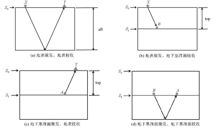
在实际应用中,地震干涉法可以用于处理各种复杂的地质构造,如高陡构造、断层、裂缝等。例如,针对近地表散射波分离问题,地震干涉法提供了一种有效的技术手段。通过将地震干涉理论与散射理论结合起来,可以导出近地表散射波地震干涉表达式,这些表达式由实际波场和背景波场干涉构成,有助于提高地震数据的信噪比和成像质量。本文提出一种面向高陡构造的地震干涉成像方法,通过将棱柱波方程代替传统的声波波动方程实现。通过图1说明本文提出方法的作用是将观测系统从地表S0下移到地下基准面S1,最终形成500 m×500 m网格数据成图(图1)。这需要输入3个观测系统下得到的炮记录,具体流程如图2~d所示。最终得到的是图2d所示的观测系统产生的炮记录。
图1
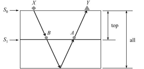
图1
基于互相关原理的双重格林函数干涉方法示意
Fig.1
Schematic of the double Green’s function interferometry method based on the cross-correlation principle
图2
传统地震干涉采用的是声波波动方程,得到的是一次反射波。不同观测系统下地震波的一次波炮记录,如式(1)~(3)所示:
式中:p0表示一次波;v表示速度;s表示震源;$\nabla^{2}$表示梯度算子。
本文提出的地震干涉采用的是棱柱波波动方程,得到的是包含高陡构造信息的多次反射波。不同观测系统下地震波的棱柱波炮记录,如式(4)~(6)所示:
式中:p0表示一次波;p1表示棱柱波;s表示震源;$\nabla^{2}$表示梯度算子;ω表示角频率;mall表示全模型偏移结果;mtop表示基准面上覆介质偏移结果。式(4)~(6)是式(1)~(3)的棱柱波表达形式。
为了简化表达,不同观测系统下地震波的棱柱波炮记录用格林函数G表达,如式(7)~(9)所示:
式(10)所示的B激发、Y接收的棱柱波炮记录与图2c所示的A激发、Y接收的棱柱波进行互相关处理;*表示取共轭。前者传播路径为B-A-Y,后者传播路径为A-Y,两者互相关处理消去A-Y,得到B激发、A接收的棱柱波炮记录,如式(11)所示:
式中:G表示格林函数;X,Y,A,B表示坐标位置;m表示地表处检波点个数;n表示地下基准面处检波点个数;i表示虚部单位;ω表示角频率。
输出校准后的格林函数并作逆傅里叶变换,将棱柱波炮记录从频率域中变换到时间域中,如式(12)所示:
式中:G表示格林函数;A,B表示坐标位置;t0表示激发时间;tmax表示人为选择的有效信号时长;ifft表示逆傅里叶变换;output表示输出。
用输出的炮记录做逆时偏移,采用互相关成像条件,如式(13)所示:
式中:I表示成像结果;S表示正传波场;R表示反传波场;x,z表示坐标位置;t表示时间;T表示总接收时间。
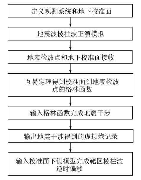
本文主要采用了两种技术,棱柱波逆时偏移和地震干涉。地震干涉的输入是炮记录,输出也是炮记录,需要将炮记录从时间域转换到频率域完成计算。计算参数是炮记录的采样点数。如果优化干涉效果,那么可以考虑对输入炮记录做汉宁窗处理,此时输入参数会额外包含汉宁窗的大小和位置。地震干涉完成后的逆时偏移处理的参数包含了网格大小,子波主频,采样间隔,采样点数。虽然输入的炮记录是做完地震干涉得到的虚拟炮记录,但是网格大小无需改变,常规逆时偏移网格大小精度即可满足本文方法。本文方法整体的技术实施方案流程如图3所示。
图3
2 模型试算
2.1 水平层状模型
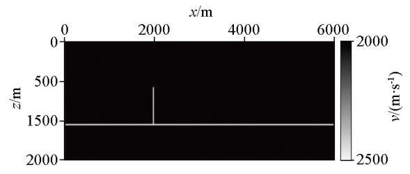
先对简单模型进行测试,如图4所示的两层水平模型,模型横向网格点数为251,纵向网格点数为251,基准面选在纵向深度1 500 m处。
图4
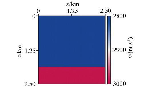
图5
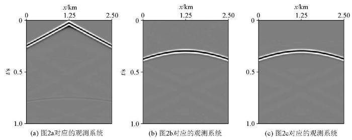
图6
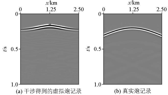
图6
两层水平模型的干涉效果炮记录对比
Fig.6
Comparison of interference effect shot records of the two-layer horizontal model
图7
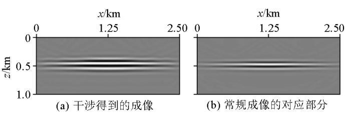
图7
两层水平模型的干涉效果逆时偏移对比
Fig.7
Comparison of reverse time migration of interference effect for the two-layer horizontal model
2.2 L模型
为了突显本文算法对棱柱波的作用,设计一个L模型,见图8所示。
图8
该模型横向600个网格点,纵向200个网格点,网格间距10 m。该模型的单炮记录见图9,由于模型较为简单,因此地震波类型较少,红色箭头和白色箭头所指的是水平地层处产生的反射波。黑色箭头所指的是棱柱波,相较于其他复杂模型,该模型的棱柱波清晰可见,因此是验证本文算法的代表性模型。
图9
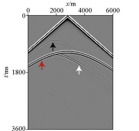
图10
2.3 盐丘模型
再对复杂模型进行测试,如图11所示的盐丘模型。
图11
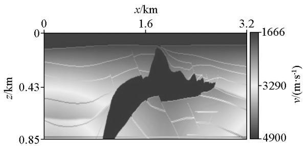
图12
图13
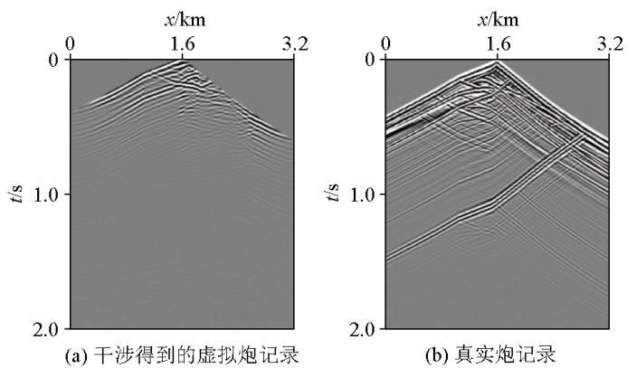
图13
盐丘模型的干涉效果炮记录对比
Fig.13
Comparison of interference effect shot records of the salt dome model
图14
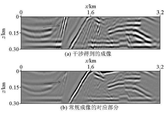
图14
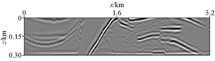
盐丘模型的干涉效果逆时偏移对比
Fig.14
Comparison of reverse time migration of interference effect for the salt dome model
图15
地震干涉的用处主要是用来降低计算成本。表1将3种计算方法进行了对比。通过表1可以看出,常规RTM的计算成本是常规干涉的5.7倍左右,证明了干涉确实减少了计算成本。棱柱波干涉的计算成本是常规干涉的1.5倍左右,但是提高了计算精度并且计算量还是小于常规RTM。在地震干涉的两次互相关运算中,地震子波发生改变,旁瓣变宽,此时如果直接将地震干涉得到的虚拟炮记录作为逆时偏移的输入炮记录进行处理,得到的剖面分辨率会降低。如果不做其他处理,那么得到的偏移结果分辨率确实无法满足超深层的生产需求。但通过地表一致性反褶积对地震子波进行压缩,压缩后的优化虚拟炮记录作为逆时偏移的输入炮记录进行处理,那么会提高地震剖面的分辨率,解决超深层的生产问题。
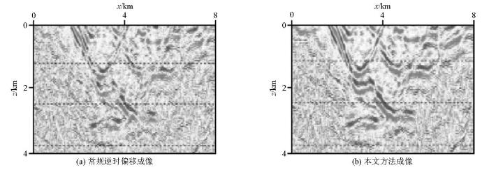
2.4 实际资料测试
图16
3 讨论
本文方法主要适用于地层倾角大于45°的高陡构造区域,如盐丘侧翼、逆冲断层带等。其有效性依赖于棱柱波的激发与传播,因此模型中存在明显的速度梯度,以确保棱柱波能够有效产生并携带陡倾角构造信息。通过数值模拟发现,速度误差超过5%时,棱柱波成像的分辨率显著下降。
本文方法考虑了计算效率和高陡构造成像问题,但整体还是基于逆时偏移技术开展的。目前还不能有效的解决起伏地表问题,粘介质问题,各向异性介质问题。其中,地震干涉只需要输入格林函数进行互相关运算,无关乎地表问题,介质问题,但棱柱波逆时偏移方程需要考虑上述问题。地震干涉相较于最近提出的Marchenko技术和最小二乘地震干涉,计算精度低,但是计算效率高,且Marchenko技术对原始输入地震资料的要求较高。因此,为了实用化,以后的研究方向考虑将地震干涉技术与人工智能相结合,将旁瓣拓宽的地震子波进行有效压缩,提高分辨率。
4 结论
观测系统下移分为两部分,第一部分是消去震源点到校准面的地震波传播路径下的反射波,第二部分是消去检波点到校准面的地震波传播路径下的反射波,这两部分都是在频率域内完成互相关计算,占比不到逆时偏移成像的百分之一,因此可忽略不计。棱柱波是一种多次波,传统成像方法中,多次波通常被视为噪声并被去除。然而,棱柱波在高陡构造的成像中具有独特优势,能够有效成像。尽管如此,棱柱波的计算量通常大于常规一次波,这在实际生产中会增加勘探成本并延长成像周期。为了在提高计算效率的同时加强高陡构造的成像精度,本文提出了一种结合地震干涉数据处理技术与棱柱波逆时偏移技术的方法。通过引入互易定理,避免了地表观测系统和地下校准面之间格林函数的二次计算,从而显著提高了计算效率。在地震干涉处理中,观测系统的下移分为两部分:消去震源点到校准面的地震波传播路径下的反射波。消去检波点到校准面的地震波传播路径下的反射波。这两部分均在频率域内完成互相关计算,其计算量仅占逆时偏移成像的不到百分之一,因此可以忽略不计。
参考文献
3D prestack wave-equation imaging-a rapidly evolving technology
[C]//Florence:
Reverse time migration
[J].
DOI:10.1190/1.1441434
URL
[本文引用: 1]

Approach may offer improvements over existing migration methods, especially in cases of steeply dipping structures with strong velocity contrasts.--Modified journal abstract.
Reversed time migration in spatial frequency domain
[J].
DOI:10.1190/1.1441493
URL
[本文引用: 1]
During the past decade, finite-difference methods have become important tools for direct modeling of seismic data as well as for certain interpretation processes. One of the earliest applications of these methods to seismics is the pioneering contribution of Alterman who, in a series of papers (Alterman and Karal, 1968; Alterman and Aboudi, 1968; Alterman and Rotenberg, 1969; Alterman and Loewenthal, 1972) demonstrated the usefulness of such numerical computations for the propagation of seismic waves in elastic media. A clear exposition of these techniques, as well as a comparison of results obtained from them with the corresponding analytical solutions, can be found in Alterman and Karal (1968). This subject was further developed and extended to more complicated models by Boore (1970), Ottaviani (1971), and Kelly et al (1976). Claerbout introduced a somewhat different finite-difference approach (Claerbout, 1970; Claerbout and Johnson, 1971) for modeling the acoustic waves which often dominate the reflection seismogram. In his approach, the original wave equation, which governs the propagation of the acoustic waves, is modified in such a way so as to allow the propagation of either only upcoming or only downgoing waves. By moving the coordinate frame with the downgoing waves, Claerbout showed that one could greatly reduce computation time. Using the same concepts, he showed (Claerbout and Doherty, 1972) how to use a similar scheme for migrating a seismic section by downward continuation of the upcoming waves. This migration method is an interesting extension of the ideas of Hagedoorn (1954) and was found to be extremely useful with real data (Larner and Hatton, 1976; Loewenthal et al, 1976).
Migration by extrapolation of time-dependent boundary VALUES
[J].DOI:10.1111/gpr.1983.31.issue-3 URL [本文引用: 1]
Iterative depth migration by backward time propagation
[C]//
Reverse-time wave-field extrapolation,imaging,and inversion
[J].
DOI:10.1190/1.1442529
URL
[本文引用: 1]
The scattered wave field propagated backward in time into an arbitrary background medium is related via a volume integral to perturbations in velocity about the background, which are expressed as a scattering potential. In general, there is no closed-form expression for the kernel of this integral representation, although it can be expressed asymptotically as a superposition of plane waves backpropagated from the receiver array. When the receiver array completely surrounds the scatterer, the kernel reduces to the imaginary part of the Green's function for the background medium.This integral representation is used to relate the images obtained by imaging algorithms to the actual scattering potential. Two such relations are given: (1) for the migrated image, obtained by deconvolving the extrapolated field with the incident field; and (2) for the reconstructed image, obtained by applying a one-way wave operator to the extrapolated field and then deconvolving by the incident field. The migrated image high-lights rapid changes in the scattering potential (interfaces), whereas the reconstructed image can, under ideal conditions, be a perfect reconstruction of the scattering potential. 'Ideal' conditions correspond to (1) weak scattering about a smoothly varying background medium, (2) a receiver array with full angular aperture, and (3) data of infinite bandwidth.Images obtained from a multioffset vertical seismic profile (VSP) illustrate some of the practical differences between the two imaging algorithms. The reconstructed image shows a much clearer picture of the target (a reef structure), in part because the one-way imaging operator eliminates artifacts caused by the limited aperture of the receiver array.
Imaging of discontinuities in the inverse scattering problem by inversion of a causal generalized Radon transform
[J].
DOI:10.1063/1.526755
URL
[本文引用: 1]
This paper treats the linearized inverse scattering problem for the case of variable background velocity and for an arbitrary configuration of sources and receivers. The linearized inverse scattering problem is formulated in terms of an integral equation in a form which covers wave propagation in fluids with constant and variable densities and in elastic solids. This integral equation is connected with the causal generalized Radon transform (GRT), and an asymptotic expansion of the solution of the integral equation is obtained using an inversion procedure for the GRT. The first term of this asymptotic expansion is interpreted as a migration algorithm. As a result, this paper contains a rigorous derivation of migration as a technique for imaging discontinuities of parameters describing a medium. Also, a partial reconstruction operator is explicitly derived for a limited aperture. When specialized to a constant background velocity and specific source–receiver geometries our results are directly related to some known migration algorithms.
Gaussian beam migration
[J].
DOI:10.1190/1.1442788
URL
Just as synthetic seismic data can be created by expressing the wave field radiating from a seismic source as a set of Gaussian beams, recorded data can be downward continued by expressing the recorded wave field as a set of Gaussian beams emerging at the earth's surface. In both cases, the Gaussian beam description of the seismic-wave propagation can be advantageous when there are lateral variations in the seismic velocities. Gaussian-beam downward continuation enables wave-equation calculation of seismic propagation, while it retains the interpretive raypath description of this propagation. This paper describes a zero-offset depth migration method that employs Gaussian beam downward continuation of the recorded wave field.The Gaussian-beam migration method has advantages for imaging complex structures. Like finite-difference migration, it is especially compatible with lateral variations in velocity, but Gaussian beam migration can image steeply dipping reflectors and will not produce unwanted reflections from structure in the velocity model. Unlike other raypath methods, Gaussian beam migration has guaranteed regular behavior at caustics and shadows. In addition, the method determines the beam spacing that ensures efficient, accurate calculations. The images produced by Gaussian beam migration are usually stable with respect to changes in beam parameters.
True-amplitude Gaussian-beam migration
[J].
DOI:10.1190/1.3052116
URL
[本文引用: 1]
Gaussian-beam depth migration and related beam migration methods can image multiple arrivals, so they provide an accurate, flexible alternative to conventional single-arrival Kirchhoff migration. Also, they are not subject to the steep-dip limitations of many (so-called wave-equation) methods that use a one-way wave equation in depth to downward-continue wavefields. Previous presentations of Gaussian-beam migration have emphasized its kinematic imaging capabilities without addressing its amplitude fidelity. We offer two true-amplitude versions of Gaussian-beam migration. The first version combines aspects of the classic derivation of prestack Gaussian-beam migration with recent results on true-amplitude wave-equation migration, yields an expression involving a crosscorrelation imaging condition. To provide amplitude-versus-angle (AVA) information, true-amplitude wave-equation migration requires postmigration mapping from lateral distance (between image location and source location) to subsurface opening angle. However, Gaussian-beam migration does not require postmigration mapping to provide AVA data. Instead, the amplitudes and directions of the Gaussian beams provide information that the migration can use to produce AVA gathers as part of the migration process. The second version of true-amplitude Gaussian-beam migration is an expression involving a deconvolution imaging condition, yielding amplitude-variation-with-offset (AVO) information on migrated shot-domain common-image gathers.
Reverse-time migration of offset vertical seismic profiling data using the excitation-time imaging condition
[J].
DOI:10.1190/1.1442041
URL
[本文引用: 1]
To apply reverse-time migration to prestack, finite-offset data from variable-velocity media, the standard (time zero) imaging condition must be generalized because each point in the image space has a different image time (or times). This generalization is the excitation-time imaging condition, in which each point is imaged at the one-way traveltime from the source to that point.Reverse-time migration with the excitation-time imaging condition consists of three elements: (1) computation of the imaging condition; (2) extrapolation of the recorder wave field; and (3) application of the imaging condition. Computation of the imaging condition for each point in the image is done by ray tracing from the source point; this is equivalent to extrapolation of the source wave field through the medium. Extrapolation of the recorded wave field is done by an acoustic finite-difference algorithm. Imaging is performed at each step of the finite-difference extrapolation by extracting, from the propagating wave field, the amplitude at each mesh point that is imaged at that time and adding these into the image space at the same spatial locations. The locus of all points imaged at one time step is a wavefront [a constant time (or phase) trajectory]. This prestack migration algorithm is very general. The excitation-time imaging condition is applicable to all source-receiver geometries and variable-velocity media and reduces exactly to the usual time-zero imaging condition when used with zero-offset surface data. The algorithm is illustrated by application to both synthetic and real VSP data. The most interesting and potentially useful result in the processing of the synthetic data is imaging of the horizontal fluid interfaces within a reservoir even when the surrounding reservoir boundaries are not well imaged.
3D acoustic prestack reverse-time migration
[J].DOI:10.1111/gpr.1990.38.issue-7 URL [本文引用: 1]
Wave-equation datuming
[J].
DOI:10.1190/1.1441010
URL
[本文引用: 1]
Wave-equation datuming is the name given to upward or downward continuation of seismic time data when the purpose is to redefine the reference surface on which the sources and receivers appear to be located. This technique differs from conventional datuming methods in the repositioning of seismic reflections laterally as well as vertically in response to observed time dips. The most interesting applications of the technique are those in which the redefined reference surface is an actual geologic interface having an irregular topography and a large velocity contrast. Wave-equation datuming can remove the deleterious effect such an interface has on seismic reflections originating below it. Wave-equation datuming also is applicable in seismic modeling.The computations required in wave-equation datuming are related to those of migration. The Kirchhoff integral formulation of the wave equation can provide a basis for computation to deal with the irregular surfaces and variable velocities that are central to the problem. The numerical implementation of the Kirchhoff approach can be reduced to an efficient procedure involving summations and convolutions of seismic traces with short shaping and weighting operators.
Wave equation datuming before stack
[J].
DOI:10.1190/1.1441620
URL
[本文引用: 1]
This note describes the extension to unstacked seismic data of a computationally efficient form of the Kirchhoff integral published several years ago. In the previous paper (Berryhill, 1979), a wave-equation procedure was developed to change the datum of a collection of zero-offset seismic traces from one surface of arbitrary shape to another, even when the velocity for wave propagation is not constant. This procedure was designated \"wave-equation datuming,\" and its applications to zero-offset data were shown to include velocity-replacement datum corrections and multilayer forward modeling. Extending this procedure to unstacked data requires no change in the mathematical algorithm. It is necessary only to recognize that operating on a common-source group of seismic traces has the effect of extrapolating the receivers from one datum to another, and that, because of reciprocity, operating on a common-receiver group changes the datum of the sources. Two passes through the data, common-source computations, then common-receiver computations, are required to change the datum of an entire seismic line before stack from one surface to another. Common-source and common-receiver trace groups must take the form of symmetric split spreads if both directions of dip are to be treated equally; reciprocity allows split spreads to be constructed artificially if the data were not actually recorded in the required form.
Elastic redatuming of multicomponent seismic data
[J].DOI:10.1111/gpr.1992.40.issue-4 URL [本文引用: 1]
Limitations of correlation-based redatuming methods
[J].DOI:10.1088/1742-2140/aa83cb URL [本文引用: 1]
Synthesis of a layered medium from its acoustic transmission response
[J].
DOI:10.1190/1.1439927
URL
[本文引用: 1]
A direct (noniterative) method is presented to determine an acoustic layered medium from the seismogram due to a time-limited plane wave incident from the lower halfspace. It is shown that one side of the autocorrelation of the seismogram due to an impulsive source at depth is the seismogram due to an impulsive source on the surface. This transforms the problem to the acoustic reflections problem as solved by Kunetz. Both the deep source time function and the layering can be determined from a surface seismogram.
Redatuming CDP data below salt with VSP Green's function
[C]//
A theoretical overview of model-based and correlation-based redatuming methods
[J].
3D target-oriented reverse-time datuming
[C]//
Bottom-up target-oriented reverse-time datuming
[C]//
Redatuming through a salt canopy and target-oriented salt-flank imaging
[J].
DOI:10.1190/1.2890704
URL
[本文引用: 1]
We describe a new shortcut strategy for imaging the sediments and salt edge around a salt flank through an overburden salt canopy. We tested its performance and capabilities on 2D synthetic acoustic seismic data from a Gulf of Mexico style model. We first redatumed surface shots, using seismic interferometry, from a walkaway vertical seismic profile survey as if the source and receiver pairs had been located in the borehole at the positions of the receivers. This process creates effective downhole shot gathers by completely moving surface shots through the salt canopy, without any knowledge of overburden velocity structure. After redatuming, we can apply multiple passes of prestack migration from the reference datum of the bore-hole. In our example, first-pass migration, using only a simple vertical velocity gradient model, reveals the outline of the salt edge. A second pass of reverse-time, prestack depth migration using full two-way wave equation was performed with an updated velocity model that consisted of the velocity gradient and salt dome. The second-pass migration brings out dipping sediments abutting the salt flank because these reflectors were illuminated by energy that bounced off the salt flank, forming prismatic reflections. In this target-oriented strategy, the computationally fast redatuming process eliminates the need for the traditional complex process of velocity estimation, model building, and iterative depth migration to remove effects of the salt canopy and surrounding overburden. This might allow this strategy to be used in the field in near real time.
Controlled-source interferometric redatuming by crosscorrelation and multidimensional deconvolution in elastic media
[J].
Source-receiver wave field interferometry
[J].DOI:10.1103/PhysRevE.81.046601 URL [本文引用: 1]
Retrieving reflections by source-receiver wavefield interferometry
[J].
Global-phase seismic interferometry unveils P-wave reflectivity below the Himalayas and Tibet
[J].
On a plane-wave based crosscorrelation-type seismic interferometry
[J].
一种高频拓展的改进地震干涉算法研究
[J].
Research on an improved seismic interferometry algorithm with high-frequency extension
[J].
