

0 引言
目前,对于CSAMT场源都是基于电偶极子源的假设,并没有考虑有限长电流线源的形态,在地形复杂的地表施工时,非直线型接地电缆源的形态会影响数据处理的结果。针对人工源电磁测深法发射源形态的影响,已有诸多研究成果;其中瞬变电磁法发射源形态的影响研究较为成熟,包括长导线源和回线源形态的影响:陈卫营等[12]阐述了电性源瞬变电磁法发射源形变对观测结果的影响,并且表明发射源的尺寸不能忽略;李展辉等[13]分析了任意形状水平接地导线源对瞬变电磁法计算结果的影响,并表示在垂直于接地导线源方向测量,尤其是进行短偏移距测量时,需考虑到导线源的具体形状,而在轴向方向测量时,在导线形变不大的情况下,可以忽略导线弯曲带来的影响;商天新等[14]考虑了野外实际工作中水平接地导线源形状的任意性,进行了任意形状水平电性源瞬变电磁法全区视电阻率计算;王鹏飞等[15]进行了不规则回线源瞬变电磁法一维正反演研究,通过沿回线积分和时频转换,计算不规则回线内任意一点处的垂直磁场值;李建平等[16⇓-18]进行了任意形状回线源瞬变电磁法研究,提出不管回线源的形状如何,只要将回线的各边看作是多个电偶极子,则回线内任意一点的电磁场均可看成是多个水平电偶极子电磁场的线性叠加,这给本文提供了宝贵的研究思路;然而以上对于发射源形态的影响研究都是基于瞬变电磁测深法展开的。针对CSAMT发射源形态的影响也有很多研究成果,但是都存在一定的局限:刘云鹤等[19]对海洋可控源电磁法发射源姿态的影响做了详细的研究,但研究结果并不能适用于地面可控源电磁法发射源形态的影响;王若等[20]对适合高山峡谷区的CSAMT的观测系统进行了研究,但却只考虑了复杂地形情况下测线的形态,并没有考虑发射源的形态;王艳波[21]对发射源起伏情况下的CSAMT进行了一维正演研究,但着重讨论的是不同收发距下发射源起伏对场值以及视电阻率和阻抗相位的影响;周子琨等[22]讨论了可控源电磁测深法在发射源导线不呈直线的情况下,测点位置视电阻率和电磁场分量的计算方法,利用直角坐标系的平移、旋转,将各个折线段产生的电磁场值转化到同一坐标系中,最后进行积分得到测点位置的总场值,然而该方法的缺陷是当发射源导线的形状较为复杂、折线段数较多时,需要进行多次坐标系的平移、旋转和电磁场分量的计算。此外,张斌等[23]进行了带地形的可控源音频大地电磁法二维正演研究,Xiong等[24]进行了带地形的二维各向异性地层中的线性源CSAMT响应模拟,但是以上学者考虑的都是测区地形起伏对观测结果的影响。目前对于复杂地形CSAMT的研究主要侧重于观测点地形的影响,而对于发射源形态的影响研究并不完善,然而诸多学者研究表明发射源形态的影响不可忽略:陈小斌等[25]在关于人工源极低频电磁波发射源的讨论中提出发射源区大地电流场的流向可能与地表线源的布设路径有关,而不是自动地选择电阻率低的区域流向另一极;刘地渊等[26]实现了任意形状线电流源三维地电场正演,正演结果表明相同模型使用倾斜线源和直线源其地表响应有较大的差别,并且任意形状线电流源更加符合实际应用情况;苏巍等[27]研究发现CSAMT的电场观测数据是由接地两端的传导分量和通电导线感应分量组成,并且感应分量贡献与传导分量贡献相当,因此在数据采集工作中必须考虑导线形状。由此可见发射源形态的影响研究值得重视,并且需要进一步完善,因此有必要进行野外实际CSAMT场源的数值模拟研究。
本文在前人研究成果的基础上,根据电磁场的线性叠加原理推导出任意电流线源激发的电磁场数值计算方法,通过模型计算,分析均匀半空间情况下折线形线源对视电阻率和阻抗相位的影响,为实际工作中的观测结果提供一定的理论指导。
1 均匀半空间线电流源的电磁场
式中:
当线源与测线呈任意方位角
其中:
图1
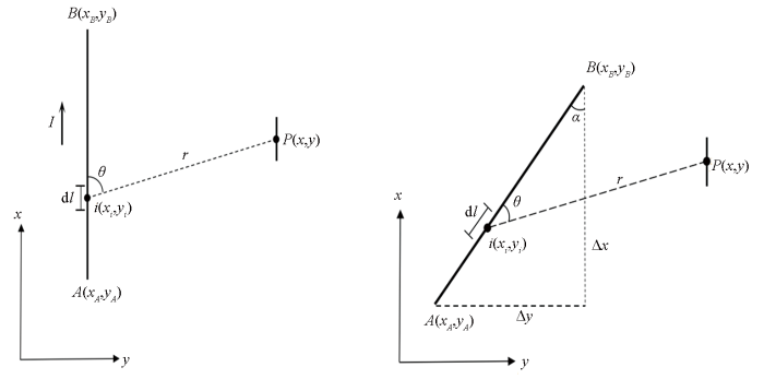
图1
电流线源与测线相对位置
a—线源与测线平行;b—线源与测线呈任意方位角
Fig.1
Relative position of current line source and survey line
a—line source parallel to the survey line;b—line source is at an arbitrary azimuth angle with the survey line
在式(4)和(5)中,需要计算定积分式:
其中:
将线源积分点的坐标
2 折线形线电流源的电磁场
其中:
图2
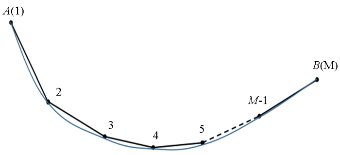
图2
任意形状电流线源剖分示意
Fig.2
Schematic diagram of the division of arbitrarily shaped current line source
式(9)和(10)分别计算电磁场,利用Cagniard视电阻率计算公式和阻抗相位计算公式即可求得不
同频率对应的视电阻率和阻抗相位。用式(11)计算Cagniard视电阻率(下文中简称为视电阻率):
用式(12)计算阻抗相位:
式中:
3 均匀半空间模型计算
3.1 任意偏角线源的影响分析
在野外进行CSAMT场源布设时,发射源应尽可能平行于测线方向布设,然而实际工作中发射源会与测线方向形成任意方位角。如图3所示,均匀半空间电阻率为100 Ω·m,发射源AB长度为1 500 m,电流强度为10 A,发射源AB与测线方向形成任意方位角
图3
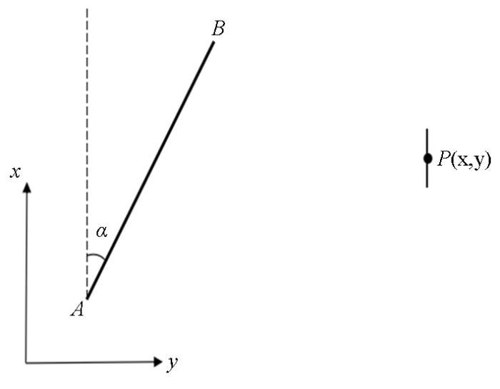
图3
发射源与测线呈任意方位角
Fig.3
The transmitting source is at an arbitrary azimuth angle to the survey line
定义相对误差的计算公式为:
其中:
图4为发射源方位角
图4
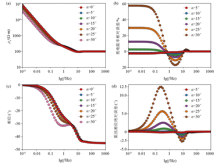
图4
发射源不同方位角对应的视电阻率和阻抗相位随频率的变化特征
a—不同方位角视电阻率随频率的变化曲线;b—不同方位角视电阻率相对误差曲线;c—不同方位角阻抗相位随频率的变化曲线;d—不同方位角阻抗相位绝对误差曲线
Fig.4
Variation characteristics of apparent resistivity and impedance phase with frequency corresponding to different azimuth angles of transmitting source
a—variation curves of apparent resistivity with frequency at different azimuth angles; b—relative error curves of apparent resistivity at different azimuth angles; c—variation curves of impedance phase with frequency at different azimuth angles; d—absolute error curves of impedance phase at different azimuth angles
==图5为发射源方位角
图5
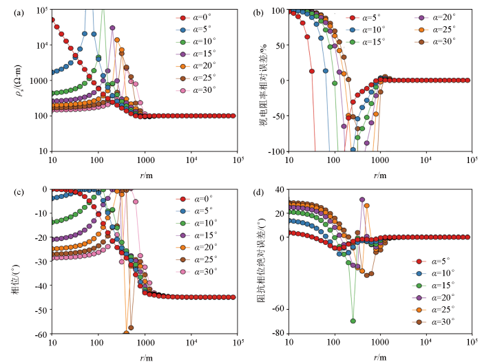
图5
发射源不同方位角对应的视电阻率和阻抗相位随收发距的变化特征
a—不同方位角视电阻率随收发距的变化曲线;b—不同方位角视电阻率相对误差曲线;c—不同方位角阻抗相位随收发距的变化曲线;d—不同方位角阻抗相位绝对误差曲线
Fig.5
Variation characteristics of apparent resistivity and impedance phase with transmit-receiving distance corresponding to different azimuth angles of transmitting source
a—variation curves of apparent resistivity with transmit-receiving distance at different azimuth angles;b—relative error curves of apparent resistivity at different azimuth angles;c—variation curves of impedance phase with transmit-receiving distance at different azimuth angles;d—absolute error curves of impedance phase at different azimuth angles
3.2 折线形线源的影响分析
折线形线源模型如图6所示,设计了3种发射源模型,保持发射源的长度不变而形态发生弯曲,将其近似为若干个折线段构成的折线形线源,每个折线段与测线方向形成的方位角都为
图6
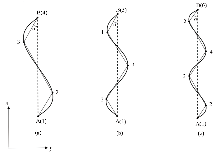
图6
折线形发射源模型示意
a—发射源模型a,节点数为4;b—发射源模型b,节点数为5;c—发射源模型c,节点数为6
Fig.6
Schematic diagram of folded line transmitting source models
a—transmitting source model a,the number of nodes is 4;b—transmitting source model b,the number of nodes is 5;c—transmitting source model c,the number of nodes is 6
发射源模型a不同折线段方位角对应的视电阻率和阻抗相位计算结果如图7、图8所示。图7a、c为视电阻率和阻抗相位随发射频率的变化曲线,b和d分别为不同方位角之间的视电阻率和阻抗相位误差曲线,收发距为8 000 m;当f>10 Hz(远区,
图7
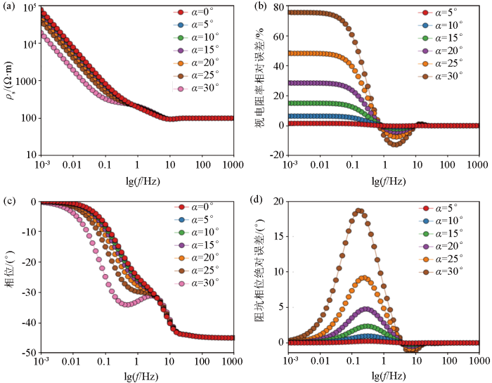
图7
折线形线源不同方位角的视电阻率、阻抗相位随频率的变化特征
a—折线形线源不同方位角视电阻率随频率的变化曲线;b—折线形线源不同方位角视电阻率相对误差曲线;c—折线形线源不同方位角阻抗相位随频率的变化曲线;d—折线形线源不同方位角阻抗相位绝对误差曲线
Fig.7
Variation characteristics of apparent resistivity and impedance phase with frequency for different azimuth angles of folded line source
a—variation curves of apparent resistivity with frequency at different azimuth angles of folded line source; b—relative error curves of apparent resistivity at different azimuth angles of folded line source; c—variation curves of impedance phase with frequency at different azimuth angles of folded line source; d—absolute error curves of impedance phase at different azimuth angles of folded line sources
图8
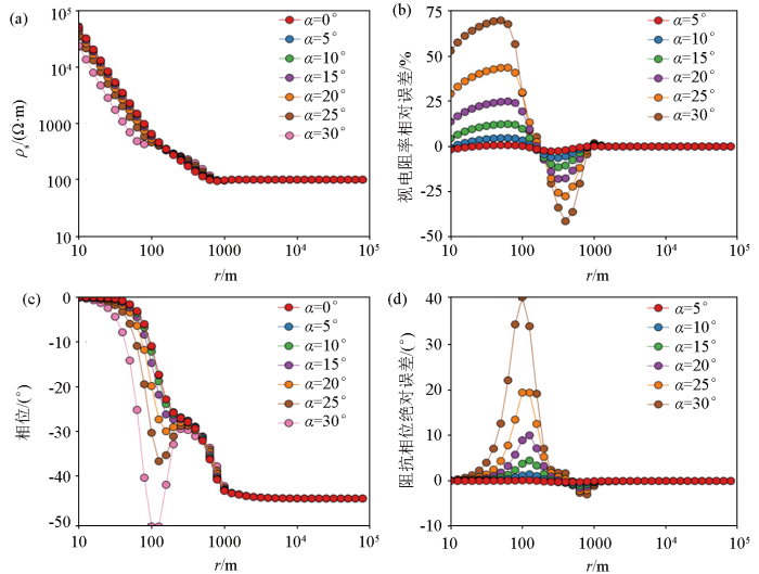
图8
折线形线源不同方位角的视电阻率、阻抗相位随收发距的变化特征
a—折线形线源不同方位角视电阻率随收发距的变化曲线;b—折线形线源不同方位角视电阻率相对误差曲线;c—折线形线源不同方位角阻抗相位随收发距的变化曲线;d—折线形线源不同方位角阻抗相位绝对误差曲线
Fig.8
Variation characteristics of apparent resistivity and impedance phase with the transmit-receiving distance for different azimuth angles of folded line source
a—variation curves of apparent resistivity with transmit-receiving distance at different azimuth angles of folded line source; b—relative error curves of apparent resistivity at different azimuth angles of folded line source; c—variation curves of impedance phase with transmit-receiving distance at different azimuth angles of folded line source; d—absolute error curves of impedance phase at different azimuth angles of folded line sources
发射源模型a、b、c在折线段方位角相同时视电阻率和阻抗相位的计算结果如图9所示,从图9中可以看出,在折线段方位角都相同的情况下,3种发射源模型计算得到的视电阻率曲线和阻抗相位曲线一致,远区视电阻率和阻抗相位的误差均为零,近区视电阻率最大误差不超过
图9
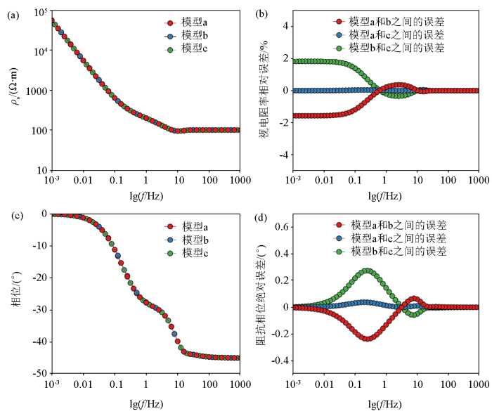
图9
不同节点数折线形线源的视电阻率、阻抗相位和误差曲线
a—发射源模型a、b、c的视电阻率曲线;b—发射源模型a、b、c之间视电阻率的相对误差曲线;c—发射源模型a、b、c的阻抗相位曲线;d—发射源模型a、b、c之间阻抗相位的绝对误差曲线
Fig.9
Apparent resistivity, impedance phase and error curves of folded line sources with different number of nodes
a—apparent resistivity curves of transmitting source models a, b and c;b—relative error curves of apparent resistivity between transmitting source models a, b and c;c—impedance phase curves of transmitting source models a, b and c;d—absolute error curves of impedance phase between transmitting source models a, b and c
图10
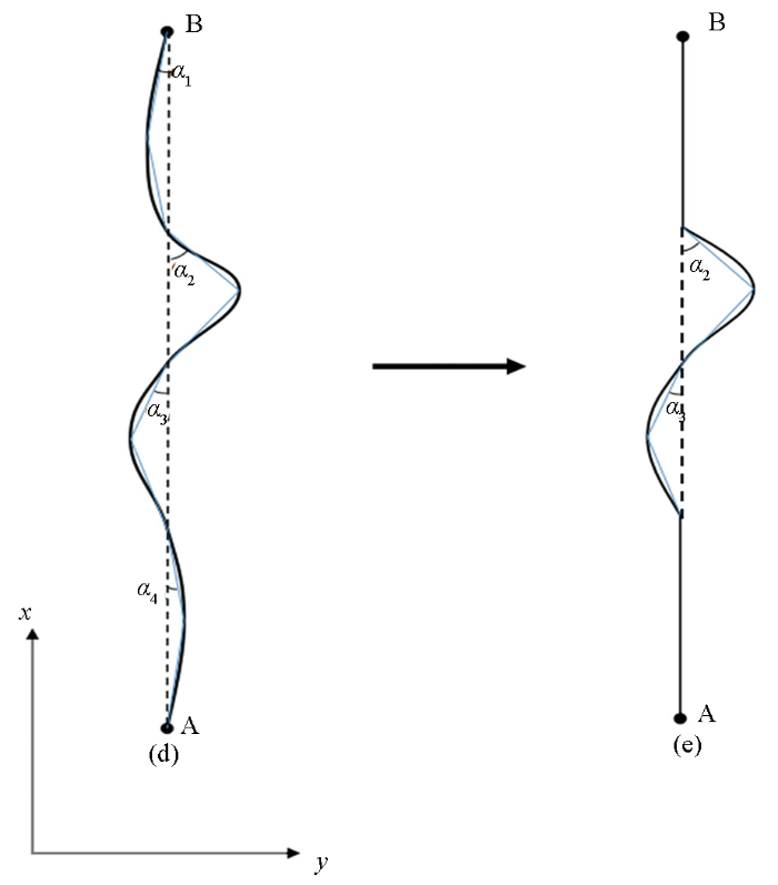
图10
折线形线源简化示意
d—任意形状折线形发射源模型;e—简化后的折线形发射源模型
Fig.10
Simplified schematic of folded line source
d—arbitrarily shaped folded line transmitting source model;e—simplified folded line transmitting source model
图11
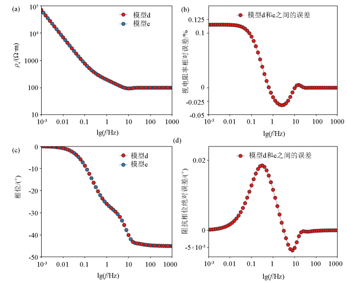
图11
折线形发射源模型简化前后的视电阻率、阻抗相位对比
a—发射源模型简化前后的视电阻率曲线;b—发射源模型简化前后视电阻率相对误差曲线;c—发射源模型简化前后的阻抗相位曲线;d—发射源模型简化前后阻抗相位绝对误差曲线
Fig.11
Comparison of apparent resistivity and impedance phase before and after simplification of folded line transmitting source model
a—apparent resistivity curves before and after transmitting source model simplification; b—relative error curve of apparent resistivity before and after transmitting source model simplification; c—impedance phase curves before and after transmitting source model simplification; d—absolute error curve of impedance phase before and after transmitting source model simplification
从图11中可以看出发射源模型d和模型e计算得到的视电阻率曲线和阻抗相位曲线相互重合,误差分析显示两种发射源模型计算得到的视电阻率误差不超过
4 结论
本文根据电磁场的线性叠加原理推导出折线形电流线源激发的电磁场数值计算方法;对于任意形状的电流线源,先将其近似为若干个折线段构成的折线形线源,再将每一个折线段剖分为多个电偶极子,最终将电偶极子的电磁场线性叠加。通过对不同的折线形线源模型计算,分析均匀半空间情况下折线形线源对视电阻率和阻抗相位曲线的影响,得到如下结论:①折线形线源只影响Cagniard视电阻率曲线和阻抗相位曲线的过渡区和近区,对远区没有影响,这种影响体现为随着折线段方位角增大,Cagniard视电阻率曲线过渡区和近区的位置向低频处偏移,而阻抗相位曲线在过渡区和近区会出现明显的畸变。②收发距越大,且折线段方位角越小时,观测结果受到的影响越小,因此应该选择合适的收发距,并尽量保持发射源与测线方向平行。③折线形线源对Cagniard视电阻率和阻抗相位曲线的影响主要是由各个折线段方位角引起的,与折线形线源的节点数(即折线段数)无关,当折线段方位角很小时,可以将其忽略并近似为直线进行处理,这样既可以充分考虑发射源的形态又可以提高工作效率。
参考文献
Audio-frequency magnetotellurics with a grounded electric dipole source
[J].
DOI:10.1190/1.1440558
URL
[本文引用: 1]

The conventional audio‐frequency magnetotelluric method has been useful in problems of shallow exploration to depths of a few kilometers. Because the natural sources are unpredictable in strength and direction, we have examined the possibility of doing magnetotelluric sounding utilizing the ratio of horizontal electric field to horizontal magnetic field from a controlled source. The source chosen for this study was a grounded electric dipole. The equations for the electric and magnetic fields around this antenna as a function of range and azimuth have been calculated for a half‐space and for a one‐layered earth. These calculations were checked for the half‐space case with an analog model and in the field at the Bonneville Salt Flats. In addition, layered cases were calculated, and a field example near Timmins, Ont., studied. Provided the distance of the observation point from the source is three skin depths (relative to the greatest resistivity in the section) or more, the conventional magnetotelluric interpretations can be applied. If the observations are closer than this, it is possible to use sets of type curves for the analysis. Such curves have been calculated. Lateral variations were studied in a model tank and by studying a massive sulfide deposit near Gooderham in Ontario.
A brief review for the proper application of magnetotelluric (MT) and controlled-source audio-frequency magnetotelluric (CSAMT) in geothermal exploration
[C]//
An application of CSAMT for detecting weak geological structures near the deeply buried long tunnel of the Shijiazhuang-Taiyuan passenger railway line in the Taihang Mountains
[J].DOI:10.1016/j.enggeo.2020.105517 URL [本文引用: 1]
Tensor CSAMT and AMT studies of the xiarihamu Ni-Cu sulfide deposit in Qinghai,China
[J].DOI:10.1016/j.jappgeo.2018.09.031 URL [本文引用: 1]
Controlled-source electromagnetic approaches for hydrocarbon exploration and monitoring on land
[J].DOI:10.1007/s10712-015-9336-0 URL [本文引用: 1]
中国人工源电磁探测新方法
[J].
New methods of controlled-source electromagnetic detection in China
[J].DOI:10.1360/SSTe-2019-0162 URL [本文引用: 1]
基于综合物探的关中眉县构造裂隙型地热水靶区预测及钻孔验证
[J].
Target area prediction and drilling verification of the tectonic fissure-hosted geothermal water in Meixian County,Guanzhong Plain based on the integrated geophysical exploration
[J].
综合物探方法在滨海县月亮湾地热资源勘查中的应用
[J].
Application of a comprehensive geophysical exploration methods in the exploration of geothermal resources in Yueliangwan,Binhai County
[J].
综合物探方法在胶东岩浆岩缺水山区找水中的应用
[J].
Application of a comprehensive geophysical exploration methods to water exploration in magmatic rock mountainous areas with water shortage in Jiaodong Peninsula
[J].
A multiple parameter extraction and electromagnetic coupling correction technique for time domain induced polarisation full waveform data
[J].DOI:10.1080/08123985.2019.1584014 URL [本文引用: 1]
电性源瞬变电磁发射源形变对观测结果影响分析
[J].
Analysis on the influence from the shape of electric source TEM transmitter
[J].
任意形状水平接地导线源瞬变电磁法一维正反演研究
[J].
1D forward modeling and inversion algorithm for grounded galvanic source TEM sounding with an arbitrary horizontal wire
[J].
任意形状水平电性源瞬变电磁全区视电阻率计算
[J].
Calculation of all-time apparent resistivity for arbitrary horizontal electrical source transient electromagnetic method
[J].
不规则回线瞬变电磁法一维烟圈反演研究
[J].
One-dimensional smoke ring inversion of irregular loop source transient electromagnetic method
[J].
层状介质任意形状回线源瞬变电磁场正反演
[J].
Tem forward and inversion of arbitrary shape loop source in layered media
[J].
层状介质任意形状回线源瞬变电磁全区视电阻率的研究
[J].
Study on the TEM all-time apparent resistivity of arbitrary shape loop source over the layered medium
[J].
不规则回线源层状介质瞬变电磁场正反演研究及应用
[J].
Study and application of the TEM forward and inversion problem of irregular loop source over the layered medium
[J].
海洋可控源电磁法发射源姿态影响研究
[J].
Attitude effect for marine CSEM system
[J].
高山峡谷区CSAMT观测系统研究
[J].
CSAMT observation system study in high mountain and steep gorge area
[J].
考虑发射源起伏的CSAMT一维正演研究
[J].
1D forward modeling of CSAMT on rolling source
[J].
不规则发射源对可控源电磁测深的影响规律
[C]//
带地形的可控源音频大地电磁法二维正演
[J].
The two-dimensional csamt modeling with topography
[J].
Linear source CSAMT response simulation in the 2D anisotropic formation with topography
[J].DOI:10.1016/j.jappgeo.2019.103861 URL [本文引用: 1]
关于人工源极低频电磁波发射源的讨论——均匀空间交流点电流源的解
[J].
Study on the transmitting mechanism of CSELF waves:Response of the alternating current point source in the uniform space
[J].
任意形状线电流源三维地电场研究
[J].
The study of three-dimensional geo-electric field of arbitrary shape line sources
[J].
均匀半空间有限长接地导线源地面电场响应特征
[J].
Characteristics of the electric field generated by a finite-length-ground wire source in homogeneous half-space
[J].
大定源回线瞬变电磁场数值滤波算法
[J].
A digital filter method for evaluating the fixed-loop transient electromagnetic field
[J].
A comparative study on the difference between the multi-dipole sources and vector synthesis source
[J].
DOI:10.32389/JEEG20-012
URL
[本文引用: 1]
CSAMT exploration generally adopts a single dipole as the transmitter. The single dipole source has the apparent disadvantages–there are weak areas for all components, Eyand Hxare weak in the area where Exand Hyare reliable. Moreover, it is hard to deploy the source with a specific direction in a rugged mountainous area. Given the shortcomings of the single dipole source, multi-dipole sources are introduced into CSAMT exploration. Although the dipole sources follow the principle of vector synthesis, the length of the source in actual exploration can last for several kilometers and the offset is generally a few kilometers. In this case, the source can no longer be regarded as a single dipole in the near-field zone. The electromagnetic field in this region becomes relatively complicated. We first compare the similarities and differences of electromagnetic field generated by vector synthesis source and multi-dipole source through the Exradiation patterns. Then, we study the factors that affect electromagnetic response due to the substitution of the double-dipole source with the vector synthesis source. The measured EM fields is affected by the source length, frequency, the source angle, the offset, and the resistivity.Finally, we apply the double-dipole source to the 1D and 3D geological model and compare the difference between the electromagnetic field generated by the double-dipole source and that generated by the vector synthesis source. Usually, the difference is very obvious in the near-field zone, and is almost negligible in the far-field zone.
CSAMT的多偶极子源特征与张量测量
[J].
Characteristics of multiple sources and tensor measurement in CSAMT
[J].
