
0 引言
海底起伏和海底浅层速度变化对OBC资料的成像质量产生重要影响,建立海底表层速度模型对浅海地区OBC资料静校正、水检和陆检资料合并、海底反射系数求取及多次波压制[13,14]等具有重要意义。目前,国内学者对浅海地区地震资料采集、噪声剔除和多次波压制等研究较多,而对浅海海底表层速度建模及其改正的研究还较少。国外学者开展了一些浅海表层速度建模方面的研究。Tanis等[15]采用回折波层析方法建立Trinidad和Azerbaijan浅海地区近海底浅层的速度模型。Zou等[16]采用拖缆记录的全波场信息,通过垂直各向异性全波形反演对Norway北海地区近海底浅层速度模型进行了反演,反演速度模型的分辨率高于反射波层析成像的结果。Abreo等[17]提出了回折波波形反演方法,并对子波估计、速度更新和质量控制进行了分析。他们将该方法应用于Colombian Caribbean地区海上地震资料,取得了较好的应用效果。为了从浅水区OBC资料中尽可能地提取出更多的有效信息来建立近海底浅层的速度模型,Wiarda等[18]提出了一种将面波反演、回折波层析成像和垂直各向异性早至波波形反演相结合的联合反演方法。该方法可以建立高精度的近海底浅层速度模型,能很好地刻画海底天然气气体转移通道等局部速度异常。Ritzwoller 和Levshin[19]采用海洋多分量地震资料对近海底浅层的横波速度和纵横波速度比进行了反演,然而该方法仅应用于一维速度模型,还有待进一步发展。
浅海地区海底浅层多为第四系沉积层,速度随深度逐渐增加。地震波在海底浅层介质中近似沿回折波射线路径传播。因此,可以利用回折波的走时和射线方程直接求解海底浅层介质的速度,避免了常规初至走时层析方法对射线追踪正演模拟的需要,从而可以提高建模效率。进行浅海OBC资料地震勘探时,海水层速度通常作为已知量,通过将位于海面附近的震源校正至海底,可以避免把海水层速度作为未知量的反演计算。基于上述考虑,文中提出针对浅海地区OBC资料的海底表层速度建模的三维初至走时反演方法,并应用于解决静校正问题。
1 表层速度建模技术
1.1 震源位置校正方法
在浅海地区进行OBC资料采集时,炮点通常位于海面附近,而检波点布设在海底,如图1所示。在近偏移距,炮检点高程差异大,不利于初至走时反演。为此,我们将震源点位从海水表面,校正至海底。而且,将炮点从海水中校正到海底,避免了对海水层速度的反演,减少了反演未知量的个数,从而有利于提高反演效果。
浅海地区炮检点间初至射线路径如图1所示。将炮点从实际位置S校正到海底S',炮点在垂直方向的校正量等于海水层的深度h,炮点沿偏移距方向的校正量为:
图1
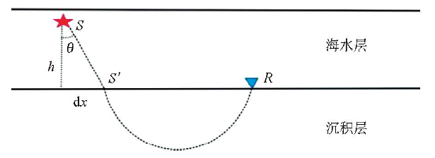
其中,θ为地震波的入射角。根据Snell定律,θ可以表示为:
其中,vsea为海水速度,p为该炮检对初至走时对应的射线参数。射线参数可以通过对初至走时沿偏移距方向求导得到。
将炮点从实际位置校正到海底,地震波走时也需要进行相应的校正。初至走时的校正量为:
由于每一条射线的射线参数都不一样,因此,对于不同的炮检对,炮点在偏移距方向的距离校正量和走时校正量不同。
为了验证震源位置校正方法的有效性,我们设计了一个两层介质的速度模型,如图1所示。炮点位于海水中,距离海底高度为15 m。检波点以10 m的间隔均匀分布在海底。海水层的速度为1 500 m/s,沉积层的速度为v(z)=1600+0.8z m/s,其中z为沉积层的厚度。
图2
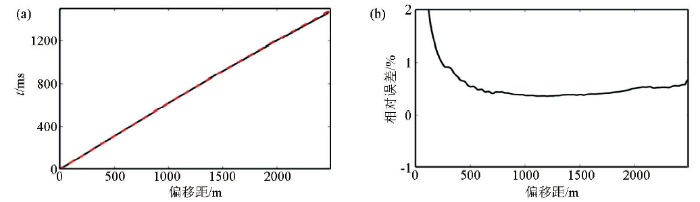
图2
走时及相对误差
a—理论走时(黑色实线)和校正后计算走时(红色虚线);b—校正后计算走时的相对误差
Fig. 2
Traveltimes and corresponding relative errors
a— theoretical traveltimes (black solid line) and corrected traveltimes (red dashed line);b—relative errors of corrected traveltimes
1.2 初至走时反演方法
浅海地区海底地形起伏平缓,海底以下地层主要为第四系沉积层,速度在纵向上随深度的增加而逐渐增加。我们假定沉积层的速度随深度线性变化,表示为:
其中,v0为海底表层速度,可以通过近道初至走时估算或者测量得到,z为沉积层的深度,β为速度随深度的变化率,v(z)为深度z处的速度。
其中,i为地震波的入射角,X为炮检点间的距离,T为初至走时。联立式(5)和式(6)消去入射角i,可以得到回折波的时距曲线方程[24]:
其中,sh-1表示双曲正弦函数的反函数。将回折波的走时和偏移距代入式(7),可求得速度随深度的变化率β。
回折波在地下介质中传播时,射线参数可表示为[26]:
其中,v(Zm)为回折点介质的速度,p为射线参数,即回折点的慢度。联立式(5)和式(8)消去入射角i,可以得到:
将偏移距X和速度随深度的变化率β代入式(9)就可以求得回折点介质的速度。然后,利用式(4)即可求得回折点的深度。
式(9)表明偏移距越大,回折点的速度和深度也越大。因此,我们首先利用小偏移距的初至走时等信息,建立浅层的速度模型。然后,结合浅层的速度模型,利用更大偏移距的初至走时信息,求取更深层的速度场。在建立深部速度场时,依据Snell定律计算出射线在浅部速度场中的传播时间和路径,然后将剩余射线路径按照回折波射线方程计算。这就只要求速度场在垂直方向的一小段内满足式(4)的常速度梯度的要求。因此,该方法适用于近海底浅层速度变化比较复杂的地区。
2 实际资料应用
2.1 工区概况
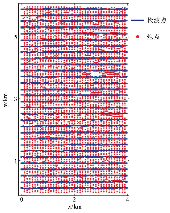
工区位于胜利油田莱州湾浅海地区,工区范围为4 km×6 km,如图3所示。在该工区内,海底起伏平缓,最小水深约为11 m,最大水深约为16.5 m。
图3
2.2 速度建模
图4
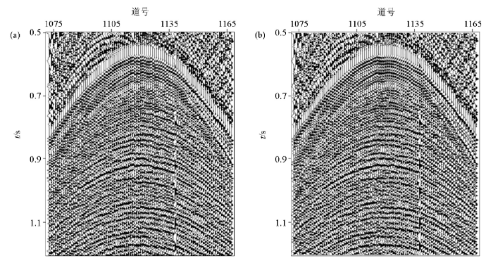
图4
静校正前(a)和静校正后(b)的单炮地震记录
Fig. 4
Shot gathers before (a) and after (b) static correction
图5
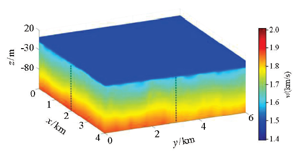
图6
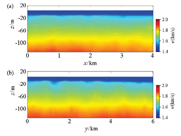
图6
速度切片
a—y方向3 km处速度剖面;b—x方向2 km处速度剖面
Fig. 6
Velocity slices
a—velocity slice at 3 km in y direction;b—velocity slice at 2 km in x direction
2.3 静校正应用
图7
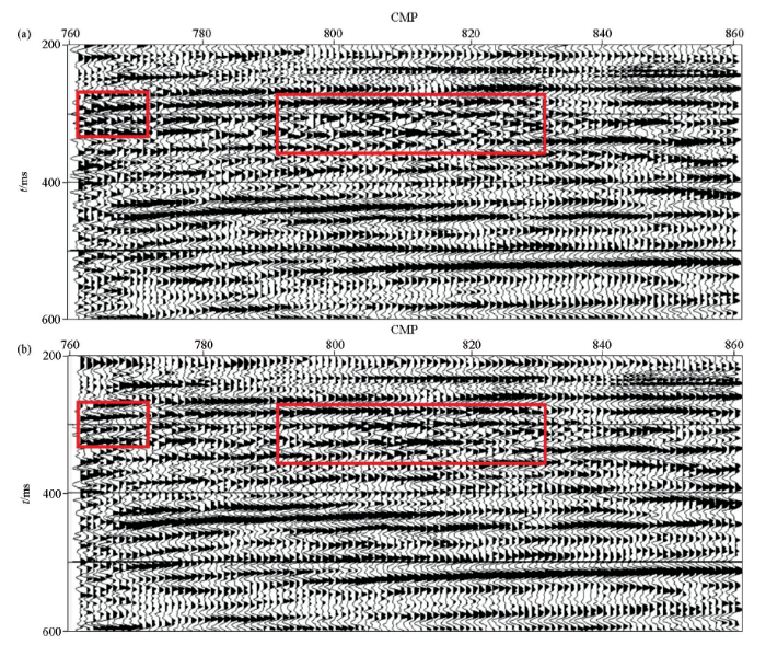
图7
静校正前(a)和静校正后(b)的叠加剖面
Fig. 7
Stack sections before (a) and after (b) static correction
图7a和7b分别为利用第18条CMP测线原始地震数据和静校正后地震数据得到的叠加剖面。对比剖面方红色方框内的同相轴,可以发现经过静校正后,同相轴聚焦更好,连续性得到了明显地改善,能量也得到了加强。
3 结论
文中针对OBC资料在浅海地区的表层速度建模问题,提出了一种浅海海底表层的速度建模方法。其中将震源从海水中的实际位置校正到海底的方法,使震源与检波点都位于海底表面,剔除了海水对初至走时的影响,避免了把海水层速度作为未知量的反演计算。
采用不同偏移距的初至走时和偏移距数据,从浅至深依次反演海底不同深度处的速度值。在逐层建立深部速度模型时,将已建立的浅部速度模型剥掉,即从初至走时和射线路径中消除在浅部速度模型中的传播时间和路径,用剩余走时和偏移距数据计算当前深度的速度值。这样,该方法不要求整个速度场而只要求局部速度场满足速度随深度线性变化,从而适用于海底浅层速度的复杂变化。
把该方法应用于胜利油田莱州湾浅海地区的实测OBC资料,建立了该地区的海底表层速度模型,并进行静校正处理,取得了良好效果,说明了该方法的有效性。
参考文献
胜利油田滩浅海地区地震勘探技术
[J].
DOI:10.3969/j.issn.1000-8918.2006.05.014
URL
Magsci
[本文引用: 1]

<p>滩浅海地区由于特殊的地表条件和复杂多变的表层结构,既不同于陆上勘探也不同于海上勘探,尤其在两栖地带存在海陆2种施工方式。笔者对滩浅海地区地震勘探的激发震源、检波器和观测系统等野外采集各环节进行了系统研究,提出解决滩浅海地区野外难以采集到高品质地震资料问题的方法,开展了地震记录上的干扰波压制、差异校正等方面的深入研究,形成一整套适用于滩浅海地区油气资源探查的高精度实用性的特色技术,取得了较好的地质效果。</p>
The application of seismic exploration technique to the beach and shallow sea area of the Shengli oil field
[J].
基于神经网络的面波迭代反演应用研究
[J].
DOI:10.3863/j.issn.1674-5086.2010.01.007
URL
[本文引用: 1]
根据滩浅海近地表结构特征,尝试利用地震记录中的面波进行近地表结构研究,以便了解滩浅海地区的近地表地层介质结构变化,为深层油气勘探提供准确的低降速带资料。针对面波频散反演已有方法存在的不足,引入一种基于BP神经网络的迭代反演方法对面波的频散曲线进行拟合迭代,用于反演预测滩浅海低降速带地层参数。由于神经网络具有很强的自学习、自适应、自组织和容错能力,它的反演预测能力非常强大,能够较精确地预测出所要求解的目标数据,同时结合传统迭代反演方法的优点,增强了该方法的反演预测能力。通过对滩浅海近地表结构模型试算,获得好的效果,同时进一步对实际记录进行了计算,也取得了比较满意的结果。
Study on the application of iterative inversion of surface wave based on artificial neural network
[J].
滩浅海地区高精度地震勘探采集方法研究
[D].
Research on high-precision seismic exploration acquisition methods in paralic zone
[D].
浅海地震勘探
[J].1959年,中国科学院海洋研究所地震队,曾在浅海进行了地震勘探工作,获得了品貭较好的地震记录,并在海上进行地震勘探工作方面取得了一些经验.下面将分别介绍这次海上地震勘探中工作方法方面,和地震记录方面的一些特点.本文所引用的实际资料均取于中国科学院海洋研究所地震队的1959年总结报告.
Shallow sea seismic exploration
[J].
滩浅海两栖地区油气地震勘探激发接收技术研究
[J].
DOI:10.3969/j.issn.1004-2903.2004.02.033
URL
Magsci
[本文引用: 1]
针对海陆两栖地区地震勘探激发、接收中存在的问题,通过改造炸药震源的装药结构和起爆方式,研制出了一种新型激发震源,提高了激发信号的品质,减小了与气枪震源之间的信号差异;在接收技术上,研制了新型压电检波器以代替常规的沼泽机电检波器,提高了接收地震信号的频率,实现了水陆相同感应机理的检波器同时接收地震信号,消除了两种不同检波器造成的信号差异;通过对两种新技术的试验分析,认为明显提高了地震资料的分辨率和信噪比,促进了海陆两栖地区地震勘探技术的发展.
Explored and receivers problem of the oil-gas seismic exploration in amphibious area
[J].
陆地节点仪器在滩浅海地震勘探中的应用研究
[J].节点地震数据采集系统是一种无线地震采集系统,根据施工区域的不同,将其分为陆地节点仪器和海底节点仪器两种。本文介绍了两种节点地震仪器的主要区别,并以陆地节点仪器Hawk为例分析了陆地节点仪器在滩浅海地震勘探中应用的可实施性,并对在实施中遇到的问题进行总结,提出了一些可参考的建议。
Application of land node instrumentation to seismic exploration in shallow sea
[J].
滩浅海地震勘探采集技术应用
[J].
DOI:10.3969/j.issn.1004-2903.2005.01.013
URL
Magsci
[本文引用: 1]
胜利油田滩浅海地区由于特殊的地表条件和复杂多变的表层结构,既不同于陆上勘探也不同于海上勘探,尤其在两栖地带存在海陆两种施工方式,如何在地震波激发和接收方面采取措施确保资料一致性,及优化观测系统设计以拼接好过渡带的地震资料是施工任务的关键.为此,依托中石化地震勘探重点基础研究实验室,在地震波的激发、接收和观测系统优化设计方面作了大量研究试验工作,形成了一套适用于滩浅海地区的地震勘探技术.通过冀东和垦东等地区应用联合表层调查和检波器精确定位等技术,有效地提高了地震资料的信噪比,改进了成像精度,取得了很好的地震勘探效果.
Seismic exploration acquisition technique application of beach shallow sea
[J].
A new 3D seismic acquisition system for very high and ultra high resolution shallow water studies
[J].
DOI:10.1046/j.1365-2397.2002.00247.x
URL
[本文引用: 1]
Click HERE to view the article.
胜利油田滩浅海地区三维高精度地震勘探采集技术研究
[D].
Research of 3D high-precision seismic exploring data acquisition technology in Shengli oil field paralic zone
[D].
胜利青东5探区滩浅海资料处理技术
[J].<p>针对青东5地区滩浅海过渡带的地表特征,在对原始资料进行详细分析和研究的基础上,采用二次定位、互相关、模型法振幅调节和叠前时间偏移等关键技术,对拖缆漂移、不同震源及检波器差异和过渡带振幅能量异常现象进行了相应的研究和针对性的处理,这些技术的应用有效消除了滩浅海资料在振幅、频率及相位等方面的不一致性,最终取得了较好的成像效果,为该区域油气勘探开发提供了有利的支持。</p>
Research on processing techniques for seismic data from the tidal zone and shallow water area of Qingdong 5 exploration zone in the Shengli oil field
[J].
胜利滩浅海地区高精度地震资料处理方法研究
[D].
Research of high-precision seismic data processing technology in paralic zone of Shengli oil field
[D].
滩浅海地区地震勘探存在问题及其解决方法
[J].
DOI:10.3969/j.issn.1000-1441.2005.04.009
URL
[本文引用: 1]
滩浅海地区地表条件复杂,陆地和海上施工方法不同,采集的资料存在着较大的差异,影响了最终成果.针对由于观测系统不同、激发和接收因素不同、海上检波器漂移等对采集资料造成的影响,探讨了改善资料品质的方法技术:①陆地采用延迟叠加震源,使陆海震源的激发信号相接近;②采用陆地压电检波器,使陆地检波器的性能与海上检波器相同;③采用匹配滤波法消除海陆资料之间存在的差异;④采用二次定位方法提高定位精度;⑤选择合适的气枪沉放深度和气枪组合方式消除气泡效应等.这些方法技术的应用,消除了陆地和海上地震资料的差异,提高了滩浅海地震资料的品质.
Problems of seismic survey in neritic area and resolved methods
[J].
桩海地区地震采集技术研究
[D].
Research of seismic acquisition technology at Zhuanghai area
[D].
浅海OBC资料自由表面多次波压制方法研究
[D].
Study on surface-related multiples attenuation of OBC data in shallow water
[D].
Diving-wave refraction tomography and reflection tomography for velocity model building
[J].
Full-waveform inversion in a shallow water environment: A North Sea 3D towed-streamer data example
[J].
Diving-wave FWI methodology applied to a Colombian Caribbean data set
[J].
Integrated surface-to-basement velocity modeling for shallow-water environments
[J].
Estimating shallow shear velocities with marine multicomponent seismic data
[J].
DOI:10.1190/1.1527099
URL
[本文引用: 1]
ABSTRACT Accurate models of shear velocities in the shallow sub-surface (<300 m depth beneath the sea floor) would help to focus images of structural discontinuities constructed, for example, with P to S converted phases in marine en-vironments. Although multicomponent marine seismic data hold a wealth of information about shear veloci-ties from the sea floor to depths of hundreds of meters, this information remains largely unexploited in oil and gas exploration. We present a method, called the multi-wave inversion (MWI) method, designed to use a wide variety of information in marine seismic data. As pre-sented here, MWI jointly uses the observed traveltimes of P and S refracted waves, the group and phase veloc-ities of fundamental mode and first overtone interface waves, and the group velocities of guided waves to in-fer shear velocities and V p /V s ratios. We show how to obtain measurements of the traveltimes of these diverse and, in some cases, dispersive waves and how they are used in the MWI method to estimate shallow shear veloc-ities. We illuminate the method with synthetic and real multicomponent marine data and apply MWI to some real data to obtain a model of V s with uncertainty es-timates to a depth of 225 m and V p /V s to about 100-m depth. We conclude by discussing the design of offshore surveys necessary to provide information about shallow shear-velocity structures, with particular emphasis on the height of the acoustic source above the sea floor.
基于早至波的特征波波形反演建模方法
[J].
DOI:10.3969/j.issn.1000-1441.2015.01.010
URL
[本文引用: 1]
近地表速度建模问题是地球物理建模的重点及难点问题。传统基于射线类的反演方法受到高频假设的限制,存在理论上的建模"盲区",而全波形反演方法的应用又受到资料品质等诸多因素的限制。介绍了一种基于全波形反演思想的特征波波形反演方法,引入早至波的概念联合初至走时层析反演,利用早至波这一特征波的运动学和动力学信息,实现对近地表及中浅层的高精度建模。模型验证结果表明,该方法即使在初始模型精度较低的情况下仍然可以达到较好的建模效果。
Characteristics waveform inversion based on early arrival wave
[J].
An overview of full-waveform inversion in exploration geophysics
[J].
Linear traveltime perturbation interpolation: a novel method to compute 3-D traveltime
[J].
DOI:10.1093/gji/ggv316
URL
[本文引用: 1]
The linear traveltime interpolation has been a routine method to compute first arrivals of seismic waves and trace rays in complex media. The method assumes that traveltimes follow a linear distribution on each boundary of cells. The linearity assumption of traveltimes facilitates the numerical implementation but its violation may result in large computational errors. In this paper, we propose a new way to mitigate the potential shortcoming hidden in the linear traveltime interpolation. We use the vertex traveltimes in a calculated cell to introduce an equivalent homogeneous medium that is specific to the cell boundary from a source. Therefore, we can decompose the traveltime at a point on the cell boundary into two parts: (1) a reference traveltime propagating in the equivalent homogeneous medium and (2) a perturbation traveltime that is defined as the difference between the original and reference traveltimes. We now treat that the traveltime perturbation is linear along each boundary of cells instead of the traveltime. With the new assumption, we carry out the bilinear interpolation over traveltime perturbation to complete traveltime computation in a 3-D heterogeneous model. The numerical experiments show that the new method, the linear traveltime perturbation interpolation, is able to achieve much higher accuracy than that based on the linear traveltime interpolation.
Fast and accurate 3-D ray tracing using bilinear traveltime interpolation and the wave front group marching
[J].
DOI:10.1111/j.1365-246x.2010.04909.x
URL
[本文引用: 1]
SUMMARY We propose a new ray tracing technique in a 3-D heterogeneous isotropic media based on bilinear traveltime interpolation and the wave front group marching. In this technique, the media is discretized into a series of rectangular cells. There are two steps to be carried out: one is a forward step where wave front expansion is evolved from sources to whole computational domain and the subsequent one is a backward step where ray paths are calculated for any source eceiver configuration as desired. In the forward step, we derive a closed-form expression to calculate traveltime at an arbitrary point in a cell using a bilinear interpolation of the known traveltimes on the cell's surface. Then the group marching method (GMM), a fast wave front advancing method, is applied to expand the wave front from the source to all girds. In the backward step, ray paths starting from receivers are traced by finding the intersection points of potential ray propagation vectors with the surfaces of relevant cells. In this step, the same TI scheme is used to compute the candidate intersection points on all surfaces of each relevant cell. In this process, the point with the minimum traveltime is selected as a ray point from which the similar step is continued until sources. A number of numerical experiments demonstrate that our 3-D ray tracing technique is able to achieve very accurate computation of traveltimes and ray paths and meanwhile take much less computer time in comparison with the existing popular ones like the finite-difference-based GMM method, which is combined with the maximum gradient ray tracing, and the shortest path method.
岩土层速度结构回折波探测原理与方法
[J].
Principle and method detecting velocity structure in rock-solid layer by reverse branch
[J].
利用地震回折波资料反演界面位置与速度分布
[J].论述了利用地震回折波资料反演 界面位置与速度分布的方法,推导了地震波走时对于界面位置偏导数的计算公式。数值模拟和实测资料的计算结果表明了该方法的有效性和编制的计算程序的实用 性。该方法最突出的特点是充分地利用了透射波资料中所含的界面位置的信息。界面位置的分辨率与界面两边的速度反差有关,速度差别越大,则分辨率越高。
Inversion of interface positions and velocity values using refracted waves
[J].
Nonlinear least-squares inversion of traveltime data for a linear velocity-depth relationship
[J].
DOI:10.1190/1.1440960
URL
[本文引用: 2]
Abstract Nonlinear least-squares inversion of traveltime data is applied to the problem of determining thickness, velocities, and velocity gradients in laterally homogeneous, horizontally layered structures. The parametric forms of the traveltime equations are used for the calculations. Results of inversions on randomly inaccurate synthetic data show that the method will not determine the gradient consistently when using reflection traveltimes. Good results are obtained, however, when using traveltimes of energy refracted in a layer by the velocity gradient. Thicknesses and average velocity in the case of reflections, or velocity at the top of the layer in the case of refractions, are also determined. Partial derivatives determined during the course of the least-squares inversion can be used to place limits on errors in the determined parameters.
