E-mail Alert Rss
 

物探与化探, 2023, 47(5): 1215-1225 doi: 10.11720/wtyht.2023.1525

方法研究·信息处理·仪器研制

瞬变电磁法勘探煤矿不同层间距双层积水采空区的可行性研究

张帆,1,2,3,4,5, 冯国瑞1,2,3,4,5, 戚庭野,1,2,3,4,5, 余传涛1, 张新军1, 王超宇1,2,3,4,5, 杜孙稳1,2,3,4,5, 赵德康1,2,3,4,5

1.太原理工大学 矿业工程学院,山西 太原 030024

2.矿山岩层控制及灾害防控山西省重点实验室,山西 太原 030024

3.山西省煤基资源绿色高效开发工程中心,山西 太原 030024

4.山西省绿色采矿工程技术研究中心,山西 太原 030024

5.山西浙大新材料与化工研究院,山西 太原 030024

Feasibility of the transient electromagnetic method in the exploration of double-layer waterlogged goafs with different layer spacings in coal mines

ZHANG Fan,1,2,3,4,5, FENG Guo-Rui1,2,3,4,5, QI Ting-Ye,1,2,3,4,5, YU Chuan-Tao1, ZHANG Xin-Jun1, WANG Chao-Yu1,2,3,4,5, DU Sun-Wen1,2,3,4,5, ZHAO De-Kang1,2,3,4,5

1. College of Mining Engineering,Taiyuan University of Technology, Taiyuan 030024,China

2. Key Laboratory of Shanxi Province for Mine Rock Strata Control and Disaster Prevention,Taiyuan 030024,China

3. Shanxi Province Coal-based Resources Green and Efficiency Development Engineering Center,Taiyuan 030024,China

4. Shanxi Province Research Center of Green Mining Engineering Technology,Taiyuan 030024,China

5. Shanxi Zhejiang University Institute of New Materials and Chemical Engineering,Taiyuan 030024,China

通讯作者: 戚庭野(1984-),男,副教授,硕士生导师,从事煤矿膏体充填开采和电法勘探的研究与教学工作。Email:qty198402@163.com

责任编辑: 叶佩

收稿日期: 2022-10-27   修回日期: 2023-02-15  

基金资助: 国家杰出青年科学基金项目(51925402)
国家自然科学基金联合基金重点项目(U1710258)
山西省科技重大专项(20201102004)
山西省科技重大专项(山西省“1331工程”)
山西省重点实验室建设项目(202104010910021)
山西浙大新材料与化工研究院研发项目(2021SX-TD001)
山西浙大新材料与化工研究院研发项目(2021SX-TD002)

Received: 2022-10-27   Revised: 2023-02-15  

作者简介 About authors

张帆(1998-),男,硕士研究生,研究方向为电磁法探测。Email:zf320425736@163.com

摘要

利用瞬变电磁法勘探上下重叠的双层积水采空区的难度较大,上部积水采空区会阻碍电磁场的传播,增加下部积水采空区的观测时间,降低信噪比,而双层积水采空区的埋深和层间距也会影响瞬变电磁信号的观测时间以及信噪比。为此,以山西马家岩煤矿为工程背景,构建了双层积水采空区模型,分析了层间距分别为25、50、75、100 m的双层积水采空区的电磁场传播过程及所需要的观测时间;使用均方根误差对不同层间距双层积水采空区的感应电压之间的差异进行了定量表述,并基于观测过程中的记录误差以及噪声水平提出下层积水采空区可勘探的判别标准。物理模拟实验结果表明:4种模型的感应电压值的差异主要集中在晚期,并且随着层间距和上层积水采空区埋深的增大,感应电压值的差异减小,层间距为75 m时感应电压之间的差异接近噪声水平;在马家岩煤矿对层间距为75 m的双层积水采空区进行了实际探测,结果表明下部积水采空区没有得到有效识别。因此,可以认为层间距大于75 m时下部积水采空区难以得到识别。

关键词: 双层采空区; 层间距; 瞬变电磁; 响应特征

Abstract

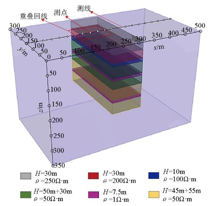
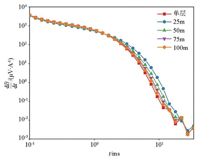
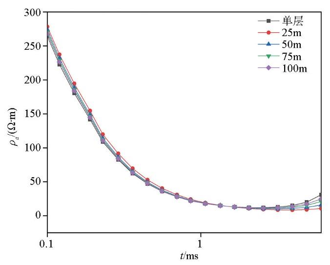
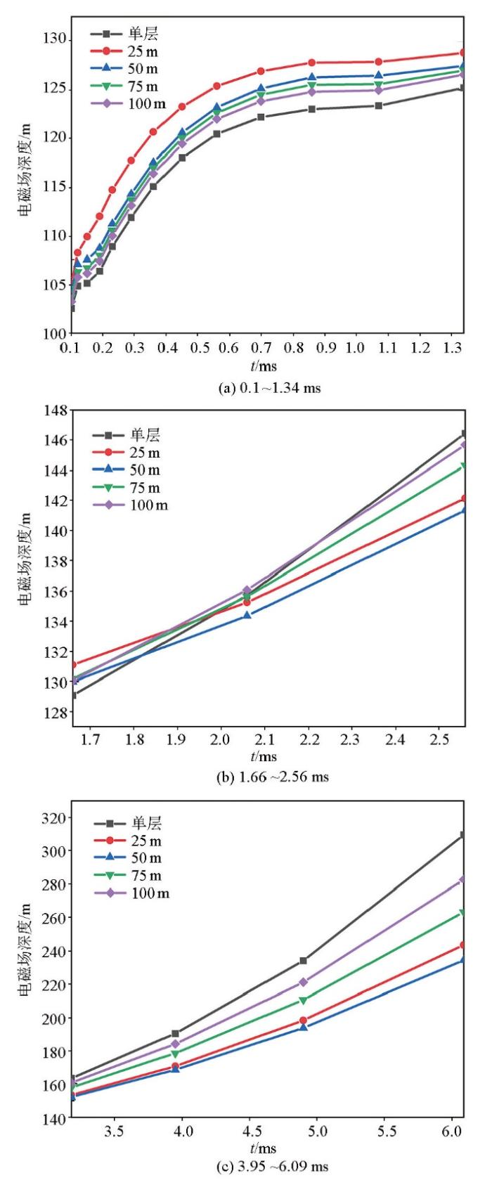
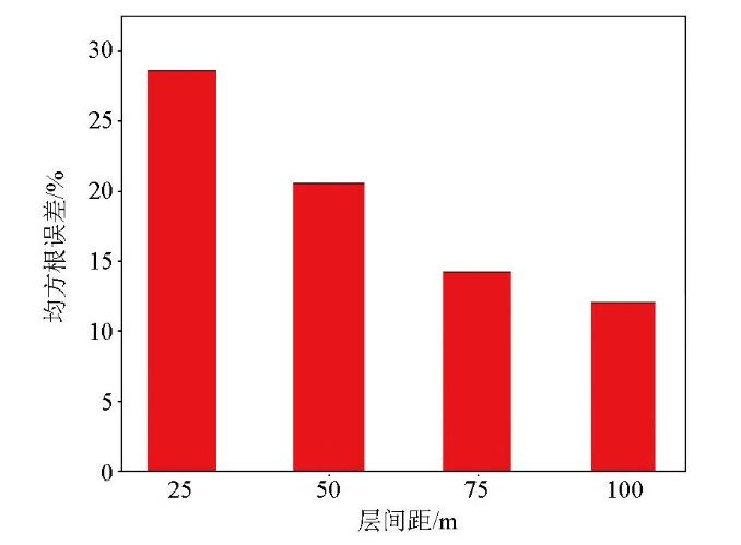
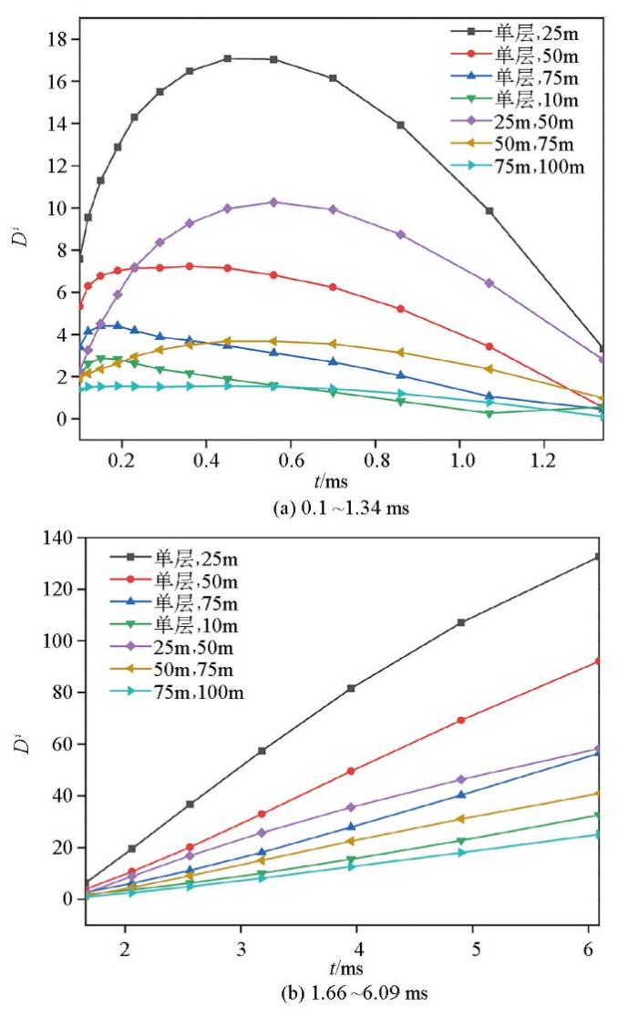
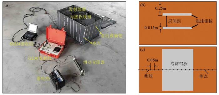
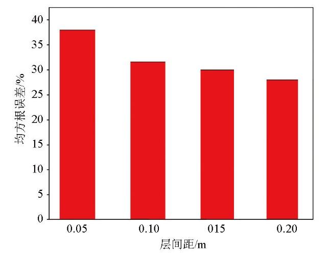
It is difficult to explore the overlapping double-layer waterlogged goafs using the transient electromagnetic method. The reason is that upper waterlogged goafs will hinder the propagation of the electromagnetic field, thus prolonging the observation of the lower waterlogged goafs and reducing the signal-to-noise ratio. Besides, the burial depths and layer spacings of double-layer waterlogged goafs affect the signal-to-noise ratio and the observation time of transient electromagnetic signals. By building a double-layer waterlogged goaf model based on the Majiayan coal mine in Shanxi, this study analyzed the electromagnetic field propagation under layer spacings of 25 m, 50 m, 75 m, and 100 m,and calculated the observation time of waterlogged goafs with different layer spacings. Furthermore, it quantitatively characterized the differences between induced voltages in the double-layer waterlogged goafs with different layer spacings using root mean square errors. Additionally, this study proposed the identification criteria for explorable lower waterlogged goafs based on the record errors and noise levels during the observation. The results of physical simulation experiments are as follows: The differences between the induced voltages of double-layered waterlogged goafs with different layer spacings occur mainly in the late stage; the differences between induced voltages gradually decrease as the layer spacing and the burial depth of upper waterlogged goafs increases; the difference between induced voltages is close to the noise level when the layer spacing is greater than 75 m. The actual detection of the double layer waterlogged goaf with a spacing of 75 meters was conducted in Majiayan Coal Mine, and the results showed that the lower waterlogged goaf was not effectively identified.Therefore, It is difficult to effectively explore the lower waterlogged goafs when the layer spacing is greater than 75 m.

Keywords: double-layer goaf; interlayer spacing; transient electromagnetic method; response characteristic

PDF (5416KB) 元数据 多维度评价 相关文章 导出 EndNote| Ris| Bibtex  收藏本文

本文引用格式

张帆, 冯国瑞, 戚庭野, 余传涛, 张新军, 王超宇, 杜孙稳, 赵德康. 瞬变电磁法勘探煤矿不同层间距双层积水采空区的可行性研究[J]. 物探与化探, 2023, 47(5): 1215-1225 doi:10.11720/wtyht.2023.1525

ZHANG Fan, FENG Guo-Rui, QI Ting-Ye, YU Chuan-Tao, ZHANG Xin-Jun, WANG Chao-Yu, DU Sun-Wen, ZHAO De-Kang. Feasibility of the transient electromagnetic method in the exploration of double-layer waterlogged goafs with different layer spacings in coal mines[J]. Geophysical and Geochemical Exploration, 2023, 47(5): 1215-1225 doi:10.11720/wtyht.2023.1525

0 引言

随着国民经济的发展,能源需求量不断增长。为了保障能源供给,我国煤炭资源开采不断向深部推进[1]。由于长期的不科学开采以及民间掠夺式采矿,形成了大量位置不明的采空区[2],造成了井下煤炭资源开采面临多层采空区的复杂现象。采空区的存在不仅影响着地层的稳定性,同时形成了地下水的存储空间,极大威胁着煤矿的安全生产[3]。瞬变电磁法由于其对低阻体的敏感性和施工效率高、受地形条件影响小等优势,被广泛应用于煤矿积水采空区的勘探[4-5]。许多学者研究了瞬变电磁法在煤矿积水采空区勘探中的应用[6-10],并且在数据处理方面取得了较大的进步[11-18]

但是,对于双层甚至多层积水采空区,由于下部积水采空区埋深较大和上部积水采空区的低阻屏蔽作用等因素,使下部积水采空区的勘探难度较大。石显新等[19]运用时域有限差分法研究了上部积水采空区对下部积水采空区的低阻屏蔽作用;侯彦威[20]研究了瞬变电磁法勘探低阻覆盖层下煤矿浅埋积水采空区的响应特征;方刚等[21]研究了瞬变电磁法勘探煤层顶板多层含水层的应用;Yan等[22]通过数值模拟方法研究了中心回线瞬变电磁法勘探多层积水采空区的可行性,并指出相比于单层积水采空区的勘探,多层积水采空区的勘探需要更长的观测时间,并且下部积水采空区的瞬变电磁响应会被上部导电层的低阻屏蔽作用削弱。由瞬变电磁法的经典理论可知,时间对应电磁场在地层中传播的深度,更长的观测时间代表着地层更深部的地质信息,同时更长的观测时间也会降低信噪比。此外,影响下部积水采空区响应时间的不仅有采空区的层数,还有下部积水采空区的埋深和双层采空区之间的层间距。因此,为了探究瞬变电磁探测大层间距双层积水采空区的问题,从经典瞬变电磁理论出发[23-25],计算了不同层间距的双层积水采空区电磁场在地层中的扩散深度,了解其随时间的变化规律,通过三维数值模拟和物理模拟手段,量化分析了煤炭多层采空区的可分辨问题,研究成果为用瞬变电磁法探测双层积水采空区提供了经验。

1 双层采空区探测的电磁场理论

发射线圈布设在地面,要实现积水采空区的勘探首先要确保电磁场传播至积水采空区处,并且接收线圈可以接收到积水采空区的电磁信号信息[26]。而且,要实现双层积水采空区中下部采空区的勘探,需要先确定在上层积水采空区低阻屏蔽作用影响下,电磁场到达下部积水采空区的时间,以及晚期瞬变电磁信号强度是否低于噪声水平以至于信号湮没在噪声中。

若发射电流采用双极性矩形脉冲波形,并且以地下某一点电场达到最大振幅作为电场到达的标志,那么电磁场在地层中的扩散深度和时间的关系可以表示为[27]

$\delta_{1}=\sqrt{\frac{2 t_{1} \rho_{1}}{\mu_{0}}},$
δi=δi-1+2tiρiμ0-2ti-1ρi-1μ0

式中:δi为在第i个测道时电磁场在地层中扩散的深度;ρ为地层电阻率;t为观测时间;μ0=4π×10-7h/m,为磁导率。在电磁场由地层浅部向地层深部传播过程中,高频部分不断衰减,随着时间的推移,低频部分占主要部分[28]。电磁场在地层中的扩散速度与频率的关系满足[29]:

v=2ωρμ0

由(3)式可知,随着时间的推移,电磁场在地层中传播的速度越来越慢,并且在高阻地层中传播速度快。因此,从发射电流关断瞬间到接收线圈接收到积水采空区的相关电磁信号所需的时间最少为τ=2t。由式(1)可以得到:

τ=δ2μ0ρ

对于大多数矿区的水平层状地层,从发射电流关断的瞬间到接收线圈接收到积水采空区的相关电磁信号所需要的时间为T=4t[27]。因此,在煤矿瞬变电磁法的应用中,式(1)、式(2)和式(4)可以分别写为

$\delta_{1}=\sqrt{\frac{T_{1} \rho_{1}}{2 \mu_{0}}},$
$\delta_{i}=\delta_{i-1}+\left|\sqrt{\frac{T_{i} \rho_{i}}{2 \mu_{0}}}-\sqrt{\frac{T_{i-1} \rho_{i-1}}{2 \mu_{0}}}\right|,$
T=2μ0δ2ρ

对于非均匀层状地层,上述公式中的ρ可以用卡尼亚电阻率ρa代替:

ρa=μ04πT2μ0LT2SR5TV2/3

式中:V为接收到的感应电压值;LT为发射线圈的边长;SR为接收线圈的等效接收面积。

2 数值模拟

2.1 数值模型建立

马家岩煤矿位于山西省太原市的西北部。勘探区域内的各地层厚度、岩性以及对钻孔视电阻率测井曲线进行统计分析所得到的视电阻率分布如表1所示。根据资料记载,在马家岩煤矿整合之前,附近小煤矿对9号煤层进行了大规模开采,并且曾经发生过洪水,致使9号煤层和4号煤层全部被淹。

表1   研究区地层概况

Table 1  Stratigraphy of the study area

地层名称厚度/m岩性视电阻率
/(Ω·m)
第四系
全新统
5~20现代冲洪积物,以砂、砾为主,中间夹有透镜状黏土层100
第四系中、
上更新统
0~70棕红色含砂黏土、淡黄色亚砂土,含钙质结核,垂直节理发育
新近系
上新统
0~75棕红色、浅紫红色黏土,亚黏土,内含砂质透镜体及钙质结核,底部为砂砾岩层200
二叠系上统
上石河子组
2~30绿色、黄绿色中粗砂砾岩与绿色、兰灰色泥岩,砂质泥岩,间夹紫色泥岩
二叠系下统
下石河子组
33~124下部岩性以灰色、灰绿色、灰黄色、灰白色、灰紫色泥岩,砂质泥岩,粉砂岩,铝质泥岩为主;上部以灰白、黄绿、灰绿色中细粒砂岩为主,间夹泥岩、砂质泥岩透镜体100
二叠系下统
山西组(含
4号煤层)
34~60灰色、灰黑色砂质泥岩,泥岩,粉、细砂岩,煤50
石炭系上统
太原组(含
9号煤层)
110~130灰色、灰黑色泥岩,砂质泥岩,粉砂岩,煤50

新窗口打开| 下载CSV


已知4号煤层和9号煤层的采高都为7.5 m左右,以表1所示的马家岩煤矿地质条件为依据,并以电阻率测井曲线得到的各个地层的电阻率作为各地层的真实电阻率,在Maxwell软件中建立不同层间距的双层积水采空区模型(图1)。采空区的平面尺寸设置为175 m×250 m,上层积水采空区的埋深为125 m,高度为7.5 m,电阻率为0.2 Ω·m;下层积水采空区的埋深分别设置为150、175、200、225 m。

图1

图1   数值计算模型

Fig.1   Numerical calculation model


2.2 数值计算结果与分析

图2所示,使用CSIRO模块进行计算,得到不同层间距的双层积水采空区正上方测点在不同时刻的感应电压值。将感应电压带入式(8)得到不同时刻的视电阻率(图3),再通过式(5)和式(6)即可得到不同时刻的电磁场扩散深度。

图2

图2   感应电压衰减曲线

Fig.2   Induction voltage decay curve


图3

图3   视电阻率计算结果

Fig.3   Apparent resistivity calculation results


使用采空区正上方测点的感应电压值计算的具体结果如图4所示,可以看到,层间距最大为100 m的双层积水采空区在第20测道6.09 ms时电磁场已经扩散至282.85 m,已经超过了下部积水采空区225 m的埋深。

图4a显示,在0.1 ~1.34 ms的时间段内单层积水采空区的电磁场扩散深度最小,扩散速度最慢,并且随着双层积水采空区层间距的增大,电磁场的扩散深度越来越接近单层积水采空区的电磁场扩散深度。图4b显示,在1.66~2.56 ms的时间段内,电磁场的扩散深度和扩散速度与层间距之间的关系发生了改变,同一时刻电磁场扩散深度不再像前一阶段和层间距呈负相关关系。在3.95 ms之后,单层积水采空区的电磁场扩散深度更大,扩散速度更快,并且随着双层积水采空区的层间距增大,电磁场的扩散深度和扩散速度都有增加的趋势(图4c)。

图4

图4   不同时间段的电磁场深度

Fig.4   Electromagnetic field depth


对照图4可知:在0.1~1. 34 ms时间段,电磁场的扩散深度约为125 m,即在第一个时间段内电磁场的扩散深度刚好到达上部积水采空区;而在1.66~2.56 ms时间段,电磁场的扩散深度刚好跨过了上部积水采空区但未到达下部积水采空区;在3.95 ms之后,电磁场的扩散深度基本大于下部积水采空区的埋深。由此可知,当电磁场传播至积水采空区时,由于电磁场在低阻体中的传播速度较慢,表现为低阻体延缓甚至阻碍电磁场向地层更深部传播,因此上层积水采空区的存在对下部积水采空区产生了低阻屏蔽作用;而当电磁场扩散深度在低阻积水采空区上部时,低阻体不仅不会延缓电磁场的传播,还会加速电磁场向地层更深部传播。

选取图2中只有上方单层采空区时的感应电压衰减情况作为对照组,不同层间距双层采空区的感应电压值在早期与单层采空区的感应电压值几乎相等,差别主要集中在晚期:层间距越小晚期感应电压值越高,而层间距越大晚期感应电压值越小且越接近单层采空区的感应电压值。这反映了近距离双层积水采空区综合叠加的涡流效应使得晚期瞬变电磁信号强度更高。

为了定量描述双层积水采空区层间距对感应电压衰减曲线的影响,将只有上部单层积水采空区时的感应电压衰减曲线作为对照组,通过式(9)分别计算不同层间距采空区感应电压值的均方根误差[30]:

χ=1Nchni=1NchnVdi-VsiSi

式中:Nchn为总测道数;Vi为第i测道的感应电压值;下标d表示双层积水采空区,下标s表示单层采空区;Si为双层、单层采空区感应电压值的平均值。

图5为不同层间距双层积水采空区的均方根误差,图中显示随着层间距的增大,感应电压值的均方根误差值减小,即层间距越大越不利于下层积水采空区的识别。层间距为75 m和100 m的感应电压衰减曲线和单层采空区的感应电压衰减曲线在整个衰减过程中重合度较高,均方根误差分别为14%和12%。

图5

图5   均方根误差

Fig.5   Root mean square error


均方根误差反映了随着层间距的增大,双层与单层积水采空区的感应电压越来越相近。而在实际的煤矿积水采空区勘探过程中,只有当感应电压衰减曲线之间的差异大于接收装置的灵敏度和环境噪声水平,才认为不同层间距的双层积水采空区可以被区分。采空区感应电压值之间的差异可以表述为

$D^{i}=\frac{2\left|V_{\mathrm{d}}^{i}-V_{\mathrm{s}}^{i}\right|}{V_{\mathrm{d}}^{i}+V_{\mathrm{s}}^{i}} \times 100 \%,$

式中:Di为第i测道的感应电压的差值;下标d、s分别表示双层积水采空区和单层积水采空区。

通过上述研究可知,6.09 ms的观测时间在理论上足够观测到下部积水采空区的瞬变电磁信号。图6显示了前20个测道(观测时间在6.09 ms之前)的Di。可以发现:在同一时刻,双层积水采空区的层间距增大则Di减小,即D单层,25 m>D单层,50 m>D单层,75 m>D单层,100 m,层间距越大,下部埋深较大的积水采空区的识别难度越大;当双层积水采空区的层间距为25 m时,在同一时刻上部积水采空区的埋深越大, Di越小,即D25 m,50 m>D50 m,75 m>D75 m,100 m;从不同时刻的Di值来看,Di值随时间先逐渐增大,约在0.45 ms时达到极大值,随后逐渐减小,约在1.34 ms时达到极小值,然后再随时间逐渐增大,直到第二十测道取得最大值。对照Di值随时间变化的过程和式(5)、式(6)计算得到的如图4所示的电磁场扩散深度随时间的变化过程可知,在Di值开始减小至极小值的时间段是电磁场逐渐靠近上部积水采空区并且到达上部积水采空区的时间,在这个时间段内感应电压主要反映上部积水采空区的信息,因此此时的Di值较小。

图6

图6   不同时间段的Di

Fig.6   Di values for different time periods


通常瞬变电磁勘探设备的灵敏度可以达到0.1~0.5 nV/m2,小于在煤矿积水采空区勘探过程中的噪声水平。因此,判断能否通过感应电压衰减曲线区分不同层间距双层积水采空区,主要还是要看Di值和噪声水平的大小关系。但是,现有的瞬变电磁勘探设备不能在观测瞬变电磁信号的同时记录现场的噪声情况,此外不同的勘探地点其噪声水平也存在差异。而在信号观测过程中的误差记录不仅是现场噪声的体现,更是噪声引起的序列误差的体现[16]。所以,用观测过程中的记录误差作为判别标准,当Di值满足

$\begin{array}{c}D^{i}>(3 \sim 5) e^{i} \\e^{i}=\max \left(\text { error }_{\mathrm{d}}^{i}, \text { error }_{\mathrm{s}}^{i}\right)\end{array}$

时,则认为通过感应电压衰减曲线可以将不同层间距的双层积水采空区进行区分。式中errordierrorsi分别表示双层、单层积水采空区的感应电压在第i测道的记录误差。

现场勘探过程中,ei大概在5%~10%之间,所以当Di大于50%时,通过感应电压衰减曲线可以将不同状态的积水采空区进行识别和区分。通过图6数据可知,层间距为25 m的双层积水采空区只有在第17测道对应的观测时间3.18 ms及之后的测道才能观察到下部积水采空区引起的瞬变电磁信号差异。层间距为50 m的双层积水采空区只有在第18测道对应的观测时间3.95 ms及之后的测道才能观察到下部积水采空区引起的瞬变电磁信号差异。而层间距为75 m的双层积水采空区从第20测道对应的观测时间6.09 ms开始才能观察到下部积水采空区引起的瞬变电磁信号差异。层间距分别为25 m和50 m的双层积水采空区也从第20测道开始采能观察到下部积水采空区引起的瞬变电磁信号差异。从图2中可以看到,对于层间距为75 m的双层积水采空区,在6.09 ms之后的感应电压值已经很接近现场勘探过程中的噪声水平,因此认为:当上层积水采空区埋深为125 m时,层间距若超过75 m则下部积水采空区不具有精准勘探的可能性。

3 物理模拟验证

由于数值计算是在完全理想的状态下进行的,其计算结果的可靠性和有效性有待进一步验证。在实际勘探过程中,很难在控制采空区大小相同和积水状态相同的情况下单独研究双层积水采空区层间距对瞬变电磁响应特征的影响,而通过物理模拟准则构建物理模拟模型,并在实验室中通过控制其他变量,单独研究双层积水采空区层间距对瞬变电磁响应特征的影响是可行的。众多学者已经验证了物理模拟方法对实际勘探具有指导意义[31-36]

3.1 物理模拟准则

从麦克思韦方程组出发进行推导,可知时间域瞬变电磁法物理模拟实验需要满足式(12)和式(13)两个模拟准则:

$\frac{\sigma_{\mathrm{m}} \mu_{\mathrm{m}} L_{\mathrm{m}}^{2}}{t_{\mathrm{m}}}=\frac{\sigma_{\mathrm{n}} \mu_{n} L_{n}^{2}}{t_{n}},$
γmμmL2mt2m=γnμnL2nt2n

式中:σ为电导率;μ为磁导率;L为线性尺度;t为采样时间;γ为介电常数;角标m代表物理模型;角标n代表数值模型或者实际现场。

在瞬变电磁物理模拟中,介质通常为无磁性的,另外数值计算和物理模拟实验采用相同的发射频率和采样时间,所以物理模拟实验只需要满足

$\frac{\sigma_{\mathrm{m}}}{\sigma_{\mathrm{n}}}=\left(\frac{L_{\mathrm{n}}}{L_{\mathrm{m}}}\right)^{2}=K^{2}$

即可。式中K为线性比例尺。

本次物理模拟实验采用1∶500的比例尺。

3.2 实验材料和过程

式(14)表明,在实验室小尺度条件下进行物理模拟实验所用到的实验材料的电阻率,应该与现场勘探和数值模拟中的岩层和积水采空区的电阻率满足一定的比例关系。

图7所示,为了使物理模拟实验系统满足物理模拟准则的要求,使用不同质量比例的水泥和石墨鳞片的均匀混合物来模拟不同电阻率的地层,使用长×宽×高为0.5 m×0.35 m×0.015 m的泡沫铝板模拟双层积水采空区。上部金属板埋深为0.25 m,下部金属板的埋深分别设置为0.3、0.35、0.4、0.45 m来模拟双层积水采空区的不同层间距。在有机玻璃箱中贴有皮尺以标定深度。有机玻璃箱长1 m,宽0.6 m,高0.5 m。采用12 V蓄电池给发射机充电,并在发射机和蓄电池之间连接滑动变阻器以控制发射电流不超过安全限值。发射机型号为GT30,接收机型号为SM24,实验中发射电流设置为1 A,发射频率设置为6.25 Hz。采用重叠回线法进行物理模拟实验,测点间距设置为0.05 m,共21个测点。发射线圈和接收线圈的规格为1 mm2漆包线,尺寸为0.2 m×0.2 m,发射线圈共20匝,电阻为1 Ω;接收线圈共40匝,电阻为2 Ω。

图7

图7   物理模拟实验装置(a)及有机玻璃箱内的正视图(b)和俯视图(c)

Fig.7   Physical simulation experimental system (a) and front view (b) and top view (c) of the organic glass box


3.3 数据分析

图8为金属板正上方测点的感应电压衰减曲线图。由于在物理模拟实验过程中会受到公频噪声和环境中的其他电磁噪声的影响,再加上多匝线圈之间的自感互感效应,早期数据出现畸变,而晚期感应电压信号值较小会湮没在噪声中。因此去除了前4个测道和最后8个测道的数据,只选取了第5测道到第20测道之间的感应电压数据,即0.23~6.09 ms的感应电压数据。

图8

图8   物理模拟感应电压衰减曲线

Fig.8   Physical simulation of induction voltage decay curve


从图中可以看到,在12测道之前即1 ms之前,不同层间距双层金属板的感应电压衰减曲线几乎重合,并且和单层金属板的感应电压衰减曲线重合。到了晚期,感应电压衰减曲线分离,层间距越小,感应电压值越高。而层间距为0.2 m的双层金属板的感应电压衰减曲线在晚期仍然和单层采空区的感应电压衰减曲线重合度较高。

图9为根据式(9)计算得到的不同层间距金属板正上方测点感应电压衰减曲线的均方根误差。可以看出,随着层间距的增大,均方根误差减小,对于下部金属板的分辨能力减弱。由于只选取了中间16个测道的感应电压值计算均方根误差,所以物理模拟实验的均方根误差值要比数值模拟中的均方根误差值要大,但是总体上均方根误差和金属板层间距呈负相关关系,这与数值计算结果相一致。

图9

图9   物理模拟均方根误差

Fig.9   Physical simulation of root mean square error


图10为物理模拟实验数据根据式(10)计算得到的Di值。可以看到,除了个别数据受到实验过程中的噪声干扰出现波动外,数据在整体上和数值计算所得到的结果相一致。在同一时刻,D单层,5 cm>D单层,10 cm>D单层,15 cm>D单层,20 cm,D5 cm,10 cm>D10 cm,15 cm>D15 cm,20 cm。在层间距一定时,Di值随时间增加先增大后减小,并在1.07 ms左右达到最小值,达到最小值的时刻与数值计算结果相吻合,这也证明了通过物理模拟实验对数值计算结果进行验证的可行性。在6.09 ms时,D单层,20 cmD 10 cm,15cmD15cm,20cm小于50,其他的Di值都大于50,这也与数值计算结果相吻合。模拟结果反映了随着层间距和上部积水采空区埋深的增大,感应电压衰减曲线之间的差异越来越小,下部积水采空区的勘探越来越困难。

图10

图10   物理模拟不同时间段的Di

Fig.10   Physical simulation Di values for different time periods


4 双层采空区现场探测

4.1 参数设定

根据马家岩煤矿以往的采煤记录,并结合研究区域的地形条件以及现场施工的难易程度等因素,在研究区域内选取了部分疑似积水采空区域进行了瞬变电磁勘探。如图11所示,整个勘探区域约2.5×10⁵ m2。使用南方灵锐S86T动态测量方法进行测点和测线的布置,在勘探区域内,测线沿ES—WN方向排列,共布设了12条测线,测线间距为40 m。单条测线内部布设了26个测点,点距为20 m,测线长500 m。

图11

图11   测网布置

Fig.11   Survey network layout


考虑到现场施工效率等因素,采用大定源回线法对部分疑似积水采空区进行了瞬变电磁勘探。为了实现更加精准的探测,在施工前先对参数设置进行了比对实验(图12),根据实验结果,选择了400 m×500 m的发射线圈和8 A的发射电流。考虑到上部积水采空区会对电磁场和等效感应涡流的传播起到延缓作用,所以采用较小的发射频率,将发射频率设置为6.25 Hz。

图12

图12   不同参数设置的实验结果对比

Fig.12   Comparison of experimental results with different parameter settings


4.2 结果分析

图13为勘探区域内第11、12号测线的反演电阻率断面。从图中可以看到,位于上部的4号煤层在横向距离0~200 m位置处被蓝色低阻区域所覆盖,此位置的电阻率较低,存在积水采空区的可能性极大,而位于4号煤层下方约75 m的9号煤层没有显现低阻特征,直观反映不存在积水采空区。

图13

图13   瞬变电测探测反演电阻率断面

Fig.13   Inversion of resistivity cross-section by transient electrical sounding


但经过地面钻探验证,发现曾发生严重突水事故的9号煤层在11、12号测线对应位置处仍然含有大量积水。由此可见,处于上方4号煤层中的大范围积水区域对相距较远的9号煤层形成了低阻屏蔽作用,再加上4号煤层和9号煤层相距较远,导致了在实测数据基础上反演得到的电阻率断面图中难以观察到9号煤层中的积水区域。

5 结论

1)以马家岩煤矿的地质条件为依据,构建了不同层间距的双层积水采空区模型;基于时间域电磁场经典理论,模拟分析了不同层间距双层积水采空区的电磁场扩散过程,发现对于双层积水采空区,地下电磁场的扩散深度和速度较为复杂。早期电磁场扩散深度小于上部积水采空区埋深时,其扩散速度和层间距呈负相关关系;中期电磁场扩散深度在上部积水采空区和下部积水采空区之间时,其扩散速度发生变化;晚期电磁场扩散深度大于下部积水采空区埋深时,其扩散速度和层间距呈正相关关系。

2) 使用均方根误差值和Di值定量描述不同层间距双层积水采空区感应电压衰减曲线之间的差异。随着层间距的增大,均方根误差值减小,下部积水采空区的分辨难度增大。而Di值随时间非单调变化,反映了电磁场的扩散过程,用实际勘探过程中的记录误差作为判别标准,认为在发射频率为6.25 Hz时在6.09 ms之后就很难观测到下部积水采空区引起的衰减曲线的异常;认为当上部积水采空区埋深为125 m时,层间距超过75 m的下部积水采空区就很难得到识别;当上部积水采空区的埋深大于175 m时,不论层间距为多少,下部积水采空区都很难得到识别。

3) 根据马家岩煤矿层间距为75 m的双层积水采空区的瞬变电磁测深结果,下部9号煤层位置处没有明显的低阻区域,但是通过钻孔验证发现9号煤层中存在范围较大的积水采空区。这验证了数值模拟和物理模拟结果的可靠性,即当上部积水采空区埋深为125 m时,层间距大于75 m的下部积水采空区很难得到有效识别。

参考文献

袁亮.

深部采动响应与灾害防控研究进展

[J]. 煤炭学报 2021, 46(3):716-725.

[本文引用: 1]

Yuan L.

Research progress of mining response and disaster prevention and control in deep coal mines

[J]. Journal of China Coal Society, 2021, 46(3):716-725.

[本文引用: 1]

赵延林, 王卫军, 赵伏军, .

多层采空区隔离顶板安全性强度折减法

[J]. 煤炭学报, 2010, 35(8):1257-1262.

[本文引用: 1]

Zhao Y L, Wang W J, Zhao F J, et al.

Strength reduction method to study safety of multilayer goafs isolation roof

[J]. Journal of China Coal Society, 2010, 35(8):1257-1262.

[本文引用: 1]

武强, 姚义, 赵颖旺, .

矿井突(透)水灾害过程中涉险人员危险性评价方法与应用

[J]. 煤炭学报, 2020, 45(7) :2357-2366.

[本文引用: 1]

Wu Q, Yao Y, Zhao Y W, et al.

An assessment of hazards to the risk-involved personnel in mine water disaster

[J]. Journal of China Coal Society, 2020, 45(7):2357-2366.

[本文引用: 1]

刘树才, 刘志新, 姜志海.

瞬变电磁法在煤矿采区水文勘探中的应用

[J]. 中国矿业大学学报, 2005, 34(4):414-417.

[本文引用: 1]

Liu S C, Liu Z X, Jiang Z H.

Application of TEM in hydrogeological prospecting of mining district

[J]. Journal of China University of Mining & Technology, 2005, 34(4):414-417.

[本文引用: 1]

欧阳涛, 底青云, 薛国强, .

利用多通道瞬变电磁法识别深部矿体—以内蒙兴安盟铅锌银矿为例

[J]. 地球物理学报, 2019, 62(5):1981-1990.

[本文引用: 1]

Ouyang T, Di Q Y, Xue G Q, et al.

Identifying deep ore bodies using the Multi-channel transient electromagnetic method (MTEM): An example of a lead-zinc-silver mine in Inner Mongolia

[J]. Chinese Journal of Geophysics, 2019, 62(5):1981-1990.

[本文引用: 1]

薛国强, 李海, 陈卫营, .

煤矿含水体瞬变电磁探测技术研究进展

[J]. 煤炭学报, 2021, 46(1):77-85.

[本文引用: 1]

Xue G Q, Li H, Chen W Y, et al.

Progress of transient electromagnetic detection technology for water-bearing bodies in coal mine

[J]. Journal of China Coal Society, 2021, 46(1):77-85.

[本文引用: 1]

杨海燕, 刘志新, 张华, .

圆锥形场源瞬变电磁法试验研究

[J]. 煤田地质与勘探, 2021, 49(6):107-112.

[本文引用: 1]

Yang H Y, Liu Z X, Zhang H, et al.

Experimental study on transient electromagnetic method with a conical source

[J]. Coal Geology & Exploration, 2021, 49(6):107-112.

[本文引用: 1]

姚伟华, 王鹏, 李明星, .

三分量地—孔瞬变电磁法积水采空区探测试验

[J]. 煤田地质与勘, 2019, 47(5):54-62.

[本文引用: 1]

Yao W H, Wang P, Li M X, et al.

Experimental study of three-component down-hole TEM for detecting water-filled goaf

[J]. Coal Geology & Exploration, 2019, 47(5):54-62.

[本文引用: 1]

薛国强, 潘冬明, 于景邨.

煤矿采空区地球物理探测应用综述

[J]. 地球物理学进展, 2018, 33(5):427-43.

[本文引用: 1]

Xue G Q, Pan D M, Yu J C.

Review the applications of geophysical methods for mapping coal-mine voids

[J]. Progress in Geophysics, 2018, 33(5):427-432.

[本文引用: 1]

侯彦威, 姚伟华.

定源回线TEM 数据的约束反演方法及应用效果

[J]. 煤田地质与勘探, 2019, 47(4):172-177.

[本文引用: 1]

Hou Y W, Yao W H.

Constrained inversion method and application effect of TEM data of fixed source loop device

[J]. Coal Geology & Exploration, 2019, 47(4):172-177.

[本文引用: 1]

刘最亮, 王鹤宇, 冯兵, .

基于电性标志层识别的瞬变电磁精准处理技术

[J]. 煤炭学报, 2019, 44(8):2346-2355.

[本文引用: 1]

Liu Z L, Wang H Y, Feng B, et al.

TEM data accurate processing technology based on electrical marker layer

[J]. Journal of China Coal Society, 2019, 44(8):2346-2355.

[本文引用: 1]

郭嵩巍, 刘小畔, 郑凯, .

基于全区视电阻率的瞬变电磁一维Occam反演中雅克比矩阵的解析算法

[J]. 物探与化探, 2020, 44(3):559-567.

[本文引用: 1]

Guo S W, Liu X P, Zheng K, et al.

Analytical algorithms of Jacobian matrix in one-dimensional Occam inversion of central loop transient electromagnetism based on all-time apparent resistivity

[J]. Geophysical and Geochemical Exploration, 2020, 44(3):559-567.

[本文引用: 1]

Woods D V. A model study of the crone borehole pulse electromagnetic(PEM) system[D]. Kingston: Queen’s University, 1975.

[本文引用: 1]

Perry A E, Gerald W H.

Influence of a conductive host on two-dimensional borehole transient electromagnetic responses

[J]. Geophysics, 1984, 49(7):861-869.

DOI:10.1190/1.1441732      URL     [本文引用: 1]

We have computed transient borehole electromagnetic (EM) responses of two‐dimensional (2-D) models using a direct and explicit finite‐difference algorithm. The program computes the secondary electric field which is defined as the difference between the total field and the primary (half‐space) field. The time derivative of the vertical magnetic field in a borehole is computed by numerical differentiation of the total electric field. These models consist of a thin horizontal conductor with a finite width, embedded in a conductive half‐space. Dual line sources energized by a step‐function current lie on the surface of the half‐space and simulate the long sides of a large rectangular loop. Numerical results substantiate several important features of the transient impulse response of such models. The peak response of the target is attenuated as the resistivity of the host decreases. A sign reversal in the secondary electric field occurs later in time as the resistivity of the host decreases. The peak response and the onset of late‐time behavior are delayed in time as well. Secondary responses for models with different host resistivities (10–1000 Ω-m) are approximately the same at late time. If the target is less conductive, the effects of the host, i.e., the attenuation and time delay, are less. It is readily apparent that there exists a time window within which the target’s response is at a maximum relative to the half‐space response. At late time the shape of the borehole anomaly due to a thin conductive 2-D target appears to be independent of the conductivity of the host. The late‐time secondary decay of the target is neither exponential nor power law, and a time constant computed from the slope of a log‐linear decay curve at late time may be much larger than the actual value for the same target in free space.

West R, Ward S.

Borehole transient electromagnetic response of a three-dimensional fracture zone in a conductive half-space

[J]. Geophysics, 1988, 53(11):1469-1478.

DOI:10.1190/1.1442427      URL     [本文引用: 1]

Borehole geophysical methods can be useful in detecting subsurface fracture zones and mineral deposits which are nearby, but not intersected by boreholes. One electrical borehole technique which can be applied to this problem is the surface‐to‐borehole transient electromagnetic (TEM) method. In this method a transmitting loop is deployed on the surface while a receiving coil is moved down a borehole. A conductive, horizontal, tabular body in a homogeneous half space was chosen to simulate a 3-D fracture zone or mineral deposit within the earth. Theoretical borehole TEM responses for several models of practical interest were computed using a direct integral‐equation formulation. The anomalous TEM response (secondary response) is the result of a complex interaction between vortex and galvanic currents within the body. Distortion of the secondary response by the conductive host does not affect the estimate of the depth to the horizontal body but it does lead to erroneous estimates of the conductivity and size of the body. Increasing the resistivity of the host decreases the host effects and increases the peak response of the body. Decreasing the separation between the body and borehole or decreasing the depth of the body increases the secondary response. The decrease in the vortex response due to the decreased coupling when a transmitting loop is offset from the body is nearly countered by an increase in the galvanic response at late times; however, this phenomenon is model‐dependent. This study indicates promise for the borehole TEM method, but the application of the technique is limited by the hardware and modest modeling capabilities presently available.

Ryu J, Morrison H, Ward S.

Electromagnetic fields about a loop source of current

[J]. Geophysics, 1970, 35:862-896.

DOI:10.1190/1.1440134      URL     [本文引用: 2]

Integral expressions for the electromagnetic field components produced by a horizontal loop, carrying a current [Formula: see text] and placed on or above the surface of an n‐layered half‐space, are deduced in a form such that numerical integration can be performed easily. The expressions are free of approximations and completely general for all frequencies. They are constrained only to the uniformity of current around the transmitting loop. The resulting computed electromagnetic fields are valid for arbitrary values of the electrical parameters σ, μ, and ε. The quasi‐static approximation for the region above the half‐space, wherein the wave equation is replaced by the Laplace equation, can be avoided. Measurements outside the loop constitute induction depth sounding. Induction depth sounding curves of field components and magnetic polarization parameters show good resolution of subsurface layering. In particular, it is suggested that the measurements of tilt angle and/or ellipticity of the magnetic polarization ellipse should be made to determine earth layering because of the rapidity and ease of these measurements in field operation. It is shown that the radius of the loop should, in the general case, be taken into account in theoretical computations. Measurements at the center of the loop constitute central induction sounding. Central induction sounding responses are diagnostic only for layered earth models in which conductivity increases with depth. Measurement of the quadrature part of the vertical magnetic field is particularly promising. Theoretical curves for earth models consisting of one layer overlying a half‐space are given for the quasi‐static case for induction depth sounding, and for the nonquasi‐static (general) case for central induction sounding. In another application, the response from a homogeneous, conductive, magnetic half‐space with the central induction method at low frequencies reveals the feasibility of in‐situ determination of static magnetic permeability. In a final application, it is shown that the effect of ground conductivity should be included in making the normal correction to Turam data whenever the apparent conductivity of the ground is greater than [Formula: see text].

Goldman M, Stoyer C.

Finite-difference calculations of the transient field of an axially symmetric earth for vertical magnetic dipole excitation

[J]. Geophysics, 2012, 48(7):953-963.

DOI:10.1190/1.1441521      URL     [本文引用: 1]

A finite‐difference formulation of the coaxial‐loop or wire‐loop transient electromagnetic (EM) prospecting systems is used to model the fields from a buried cylindrical conductor whose axis is coincident with that of the field system. Solutions are obtained directly in the time domain. The formulation is implicit and two‐dimensional (2-D) in space. The variable‐directions method reduces each advance of one step in time from one 2-D problem to a large number of one‐dimensional (1-D) problems. The result is a reduction in computational effort. In order to avoid including the air in the finite‐difference grid, an integral equation approach is used to formulate the surface boundary condition. Thus, two sets of 1-D finite‐difference solutions and one Fredholm integral equation solution are required for each step forward in time. Comparison with analytical solutions shows excellent agreement in the case of a four‐layer earth. All computations were carried out for a perfectly conducting basement, but the method can be used for finitely conducting basement as well. If the basement is an insulator, an additional integral equation solution is required on the lower boundary. Results for a buried cylindrical conductor show that there is a high degree of sensitivity to conductor size. Inversion of transients to a stratified model can be useful if the effect of finite conductor size is taken into account. For cylindrical conductors with lateral extent comparable to or larger than the source‐receiver separation, the inversion results are valid. For conductors with lateral extent small compared with source‐receiver separation, the inversion will yield a stratified model which shows better agreement between actual and inverted thicknesses than resistivities. The involved resistivities are somewhat higher than those actually present in this case.

King A.

Cindered coal detection using transient electromagnetics methods

[J]. Geoexploration, 1987, 24(4/5):367-379.

DOI:10.1016/0016-7142(87)90007-X      URL     [本文引用: 1]

石显新, 闫述, 陈明生.

瞬变电磁勘探中的低阻层屏蔽问题

[J]. 煤炭学报, 2005, 30(2):160-163.

[本文引用: 1]

Shi X X, Yan S, Chen M S.

Study on screening of conductive bed in transient electromagnetic prospecting

[J]. Journal of China Coal Society, 2005, 30(2):160-163.

[本文引用: 1]

侯彦威.

TEM探测低阻覆盖层下煤矿浅埋积水采空区

[J]. 煤炭工程, 2020, 52(5):101-105.

[本文引用: 1]

Hou Y W.

TEM detection of goaf with shallow water under low resistivity overburdens

[J]. Coal Engineering, 2020, 52(5):101-105.

[本文引用: 1]

方刚, 高波.

榆横北区地面瞬变电磁法探查含水层特征应用

[J]. 中国煤炭, 2018, 44(11):30-35.

[本文引用: 1]

Fang G, Gao B.

Application of the ground transient electromagnetic method in detecting aquifer characteristics in northern Yuheng mining area

[J]. China Coal, 2018, 44(11):30-35.

[本文引用: 1]

Yan S, Xue G Q, Qiu W Z, et al.

Feasibility of central loop TEM method for prospecting multilayer water-filled goaf

[J]. Applied Geophysics, 2016, 13(4):427-432.

[本文引用: 1]

Kaufman A, Keller G V. Frequency and transient[M]. New York: Elseviser Science Publishing Company Inc, 1983:213.

[本文引用: 1]

Hohmann G, Raiche A. Inversion of controlled source electromagnetic data[M]. Beijing: Geological Publishing House, 1992:452-486.

[本文引用: 1]

Zhdanov M. Geophysical electromagnetic theory and methods[M]. New York: Elsevier Science Publishing Company Inc, 2009:153-231.

[本文引用: 1]

闫述, 陈明生, 傅君眉.

瞬变电磁场的直接时域数值分析

[J]. 地球物理学报, 2002, 45(2):275-284.

[本文引用: 1]

Yan S, Chen M S, Fu J M.

Direct time-domain numerical analysis of transient electromagnetic fields

[J]. Chinese Journal of Geophysics, 2002, 45(2):275-284.

[本文引用: 1]

Spies B R.

Depth of investigation in electromagnetic sounding method

[J]. Geophysics, 1989, 54(7):872-888.

DOI:10.1190/1.1442716      URL     [本文引用: 2]

The time or frequency at which the electromagnetic (EM) response of a buried inhomogeneity can first be measured is determined by its depth of burial and the average conductivity of the overlying section; it is relatively independent of the type of source or receiver and their separation. The ability to make measurements at this time or frequency, however, depends on the sensitivity and accuracy of the instrumentation, the signal strength, and the ambient noise level. These factors affect different EM sounding systems in surprisingly different ways. For the magnetotelluric (MT) method, it is possible to detect a buried half‐space under about 1.5 skin depths of overburden. The maximum depth of investigation is virtually unbounded because of high signal strengths at low frequencies. Transient electromagnetic (TEM) soundings, on the other hand, have a limited depth of penetration, but are less affected by static shift errors. For TEM, a buried inhomogeneity can be detected under about one diffusion depth of overburden. For conventional near‐zone sounding in which induced voltage is measured (impulse response), the depth of investigation is proportional to the [Formula: see text] power of the source moment and ground resistivity. By contrast, if the receiver is a magnetometer (step response system), the depth of investigation is proportional to the [Formula: see text] power of source moment and is no longer a function of resistivity. Magnetic‐field measurements may, therefore, be superior for exploration in conductive areas such as sedimentary basins. Far‐zone, or long‐offset, TEM soundings are traditionally used for deep exploration. The depth of investigation for a voltage receiver is proportional to the [Formula: see text] power of source moment and resistivity and is inversely proportional to the source‐receiver separation. Magnetic‐field measurements are difficult to make at long offsets because instrumental accuracy limits the measurement of the very slow decay of the magnetic field. Frequency‐domain controlled‐source systems are ideally suited for sounding at the very shallow depths needed for engineering, archaeological, and groundwater applications because of the relative ease of extending the measurements to arbitrarily high frequencies, and also because geometric soundings can be made at low induction numbers.

闫述, 石显新, 陈明生.

瞬变电磁法的探测深度问题

[J]. 地球物理学报, 2009, 52(6):1583-1591.

[本文引用: 1]

Yan S, Shi X X, Chen M S.

The probing depth of transient electromagnetic field method

[J]. Chinese Journal of Geophysics, 2009, 52(6):1583-1591.

[本文引用: 1]

Stratton J. Electromagnetic theory[D]. McGraw-Hill Book Company, 1941.

[本文引用: 1]

Li H, Xue G Q, Zhou N N, et al.

Appraisal of an array TEM method in detecting in a mined-out area beneath a conductive layer

[J]. Pure and Applied Geophysics, 2015, 172(10):2917-2929.

DOI:10.1007/s00024-015-1075-0      URL     [本文引用: 1]

姜志海, 焦险峰.

矿井瞬变电磁超前探测物理实验

[J]. 煤炭学报, 2011, 36(11):1852-1857.

[本文引用: 1]

Jiang Z H, Jiao X F.

Physical experiment of mine transient electromagnetic advanced detection

[J]. Journal of China Coal Society, 2011, 36(11):1852-1857.

[本文引用: 1]

姜志海, 杨光.

浅埋特厚小窑采空区瞬变电磁探测技术研究及应用

[J]. 采矿与安全工程学报, 2014, 3(5):769-774.

[本文引用: 1]

Jiang Z H, Yang G.

Research and application of TEM detection technology for small mine gob area in shallowly-buried and extremely thick seam

[J]. Journal of Mining & Safety Engineering, 2014, 3(5):769-774.

[本文引用: 1]

焦险峰, 刘志新.

瞬变电磁法浅层分辨物理模拟实验研究

[J]. 中国矿业大学学报, 2014, 43(4):738-741.

[本文引用: 1]

Jiao X F, Liu Z X.

Physical model and experimental research on shallow resolution of transient electromagnetic method

[J]. Journal of China University of Mining & Technology, 2014, 43(4):738-741.

[本文引用: 1]

陈载林.

瞬变电磁法几种规则形体的物理模拟实验

[J]. 物探与化探, 2013, 37(6):1092-1095.

[本文引用: 1]

Chen Z L.

Physical simulation experiments on several regular shapes of transient electromagnetic method

[J]. Geophysical and Geochemical Exploration, 2013, 37(6):1092-1095.

[本文引用: 1]

王欣.

曙光煤矿瞬变电磁超前探测物理模拟试验研究

[J]. 机械管理开发, 2018, 33(7):143-144,147.

[本文引用: 1]

Wang X.

Experimental study on physical simulation of Transient Electromagnetic advanced detection in Shuguang Coal Mine

[J]. Mechanical Management and Development, 2018, 33(7):143-144,147.

[本文引用: 1]

许时昂, 孙松, 韩鹏飞, .

瞬变电磁重叠覆盖超前探水模拟测试研究

[J]. 工程地球物理学报, 2014, 11(1):40-43.

[本文引用: 1]

Xu S A, Sun S, Han P F, et al.

Simulation and test study of the overlapping coverage of detecting water in advance by transient electromagnetic method

[J]. Chinese Journal of Engineering Geophysics, 2014, 11(1):40-43.

[本文引用: 1]

/

京ICP备05055290号-3
版权所有 © 2021《物探与化探》编辑部
通讯地址:北京市学院路29号航遥中心 邮编:100083
电话:010-62060192;62060193 E-mail:whtbjb@sina.com , whtbjb@163.com